Showing posts with label Android. Show all posts

Android operating system in electronics projects

  Android operating system in electronics projects

We are witnessing the growing influence of the Android operating system. The intensity of the growth of mobile devices with the Android OS is growing exponentially. Android has a large community of developers writing applications ("apps") that extend the functionality of the devices. Developers write primarily in a customized version of Java. Apps can be downloaded from third-party sites or through online stores such as Android Market, the app store run by Google. As of October 2011 there were more than 400,000 apps available for Android, and the estimated number of applications downloaded from the Android Market as of December 2011 exceeded 10 billion. So, in that amount of applications, engineers can find many useful things that can help us at any time. Since our fields of interest include microcontrollers and electronics in general, we recommend the following applications.

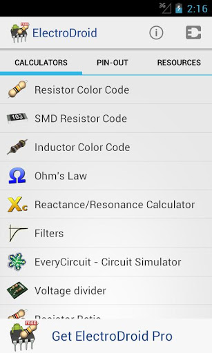
 ElectroDroid. Powerful collection of electronics tools and reference. A must for any enthusiast. ElectroDroid is a simple and powerful collection of electronic tools and references; it includes:
• Resistor color code decoder (3-6 bands);
• Inductor color code decoder;
• Ohm’s law calculator;
• Reactance calculator;
• Voltage divider;
• Resistor ratio, value/series/parallel;
• Capacitor charge calculation;
• Operational amplifier;
• LED resistor calculator;
• LM317 calculator;
• Heat dissipation;
• Battery Life calculator;
• Inductor design tool;
• Voltage Drop calculator;
• PCB Trace Width calculator;
• Simple Filters calculator;
• NE555 astable calculator;
• Port pin-out (USB, Serial, Parallel, Ethernet, SCART, DVI, HDMI, S-Video, VGA, FireWire, Jack, XLR, RCA, DMX, ATX, Molex, EIDE, SATA);
• Resources (Resistivity table; Table of standard resistors and capacitors; Capacitor marking codes; AWG and SWG Wire size; Ampacity Table; Symbols and Abbreviations; Circuit Schematic Symbols; SI Units prefixes; Battery info; Boolean logic gate and algebra Theorems; 7400 info and pinout; ASCII code);
• Full support for EIA resistor series for all caluculators;
...and more to come!
 For more information visits link: http://electrodroid.demisoft.it or here.
 Similar application: Electronics Toolkit, Electric Toolkit, Ohm’s Law PLUS, Droid Tesla, Resistor Tool, Electrical Pro.
Also you can find always needy applications for NE555 chip: NE555 Timer Tool and 555 Calculator.
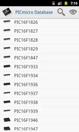
 PICMicro Database. PICmicro database allow you to check the characteristics of all the PIC and dsPIC microcontrollers produced by Microchip. You can search for your favorite microcontroller, reading the features, applying filters, and many new features will be introduced in future versions...
More information here.

 Blue Control. Blue Control is a basic universal Remote Control for Blue-Tooth enabled serial devices such as Blue Tooth modules connected to a micro-controller.For each button pressed the corresponding ASCII code for the label will be sent. For example pressing buttons A-H will send the charactes "a" - "h".The up, down, left, right, and center buttons will send "U","D","L","R", and "C" characters. Hopefully this will inspire people to create alot of fun Blue-Tooth Controlled devices.More information here.

[REPORT] android based blue tooth controlled device


Blue Temp. BlueTemp connects Android to a temperature sensor device that can be built with a DS18B20 temperature sensor, an MSP430G2553 microcontroller, and a BlueSMiRF Bluetooth module. The schematics and firmware to build the device can all be downloaded from http://www.mikekohn.net/micro/bluetooth_thermometer.php along with an explanation how it works.
 IOIO for Android. The IOIO (pronounced "yo-yo") is a board specially designed to work with your Android 1.5 and later device. The board provides robust connectivity to an Android device via a USB or Bluetooth connection and is fully controllable from within an Android application using a simple and intuitive Java API - no embedded programming or external programmer will ever be needed. Check our article about IOIO.
 ORDROID ADK Demo. In the near future any evaluation kit will probably be supplied with Android App. This is one example. The ODROID-ADK is a microcontroller board based on the PIC24FJ64GB002-I/ML from Microchip. It has an embedded USB host interface to connect with Android Smartphone directly or Bluetooth adaptor. It has 11 digital input/output pins (of which 5 can be used as PWM outputs), 3 analog inputs, Li-polymer battery charger, a USB connection, a 5Volt DC/DC converter for USB Bus power, a power jack(USB Mini-B), an ICSP header, a pressure sensor to measure altitude and a power switch. Here how it looks.

Audio Serial Out. Control any serial device from your phone. Output serial commands from the audio port. You can control any serial device from your android phone without rooting or bluetooth. More information here. Here you can see how it looks.

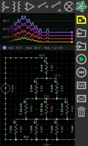
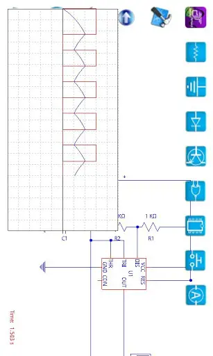
EveryCircuit Free. Design and simulate electronic circuits. All joking aside, this time you will understand how electronic circuits work. Build any circuit, tap play button, and watch dynamic voltage and current animations. This gives you insight into circuit operation like no equation does. While simulation is running, adjust circuit parameters with analog knob, and the circuit responds to your actions in real time. You can even generate an arbitrary input signal with your finger. For more information click here. Watch the video.
OsciPrime Oscilloscope. This is the Open Source Oscilloscope based on the Bachelor Thesis "Using Android in Industrial Automation" of the University of Applied Sciences of Northwestern Switzerland. It will use the microphone as input source, "USB" will only work with the hardware board from our project. For more information, click here. Similar application is Oscilloscope Pro, but it is not free.
Stay tuned for more applications soon that we will find and test for you.
Team of Electronics-Base.com


if u like the post just say thank u in comment box.

[REPORT] Smart phone Android Operated Robot ,WIRELESS,BLUETOOTH


Some Importantant links below with reports.just view the link below. if u want any project report just search any project on our search box
Arduino interesting projects:   
Arduino 30 simple and good projects 
Atmega projects lists
Android Electronics projects lists
Rf based Projects with report
engineering study notes 
GSM GPS based projects with report
Bluetooth based projects with reports


Smart phone Android Operated Robot

The project aims in designing a Robot that can be operated using Android mobile
phone. The controlling of the Robot is done wirelessly through Android smart phone
using the Bluetooth feature present in it. Here in the project the Android smart phone is
used as a remote control for operating the Robot.
Android is a software stack for mobile devices that includes an operating system,
middleware and key applications. Android boasts a healthy array of connectivity options,
including Wi-Fi, Bluetooth, and wireless data over a cellular connection (for example,
GPRS, EDGE (Enhanced Data rates for GSM Evolution), and 3G). Android provides
access to a wide range of useful libraries and tools that can be used to build rich
applications. In addition, Android includes a full set of tools that have been built from the
ground up alongside the platform providing developers with high productivity and deep
insight into their applications.
Bluetooth is an open standard specification for a radio frequency (RF)-based,
short-range connectivity technology that promises to change the face of computing and
wireless communication. It is designed to be an inexpensive, wireless networking system
for all classes of portable devices, such as laptops, PDAs (personal digital assistants), and
mobile phones. It also will enable wireless connections for desktop computers, making
connections between monitors, printers, keyboards, and the CPU cable-free.
The controlling device of the whole system is a Microcontroller. Bluetooth
module, DC motors are interfaced to the Microcontroller. The data received by the
Bluetooth module from Android smart phone is fed as input to the controller. The
controller acts accordingly on the DC motors of the Robot. The robot in the project can
be made to move in all the four directions using the Android phone. The direction of the
robot is indicated using LED indicators of the Robot system. In achieving the task the
controller is loaded with a program written using Embedded ‘C’ language.

Proposal Smart phone Android Operated Robot

Some Importantant links below with reports.just view the link below. if u want any project report just search any project on our search box
Arduino interesting projects:   
Arduino 30 simple and good projects 
Atmega projects lists
Android Electronics projects lists
Rf based Projects with report
engineering study notes 
GSM GPS based projects with report
Bluetooth based projects with reports


Smart phone Android Operated Robot

The project aims in designing a Robot that can be operated using Android mobile
phone. The controlling of the Robot is done wirelessly through Android smart phone
using the Bluetooth feature present in it. Here in the project the Android smart phone is
used as a remote control for operating the Robot.
Android is a software stack for mobile devices that includes an operating system,
middleware and key applications. Android boasts a healthy array of connectivity options,
including Wi-Fi, Bluetooth, and wireless data over a cellular connection (for example,
GPRS, EDGE (Enhanced Data rates for GSM Evolution), and 3G). Android provides
access to a wide range of useful libraries and tools that can be used to build rich
applications. In addition, Android includes a full set of tools that have been built from the
ground up alongside the platform providing developers with high productivity and deep
insight into their applications.
Bluetooth is an open standard specification for a radio frequency (RF)-based,
short-range connectivity technology that promises to change the face of computing and
wireless communication. It is designed to be an inexpensive, wireless networking system
for all classes of portable devices, such as laptops, PDAs (personal digital assistants), and
mobile phones. It also will enable wireless connections for desktop computers, making
connections between monitors, printers, keyboards, and the CPU cable-free.
The controlling device of the whole system is a Microcontroller. Bluetooth
module, DC motors are interfaced to the Microcontroller. The data received by the
Bluetooth module from Android smart phone is fed as input to the controller. The
controller acts accordingly on the DC motors of the Robot. The robot in the project can
be made to move in all the four directions using the Android phone. The direction of the
robot is indicated using LED indicators of the Robot system. In achieving the task the
controller is loaded with a program written using Embedded ‘C’ language.

[ ANDROID ] 30 PROJECTS

Contents

Acknowledgments . . . . . . . . . . . . . . . . . . . . . . . . . . . . . . . . . . . . . . . . . . . . . . . . . . ix

Introduction . . . . . . . . . . . . . . . . . . . . . . . . . . . . . . . . . . . . . . . . . . . . . . . . . . . . . . . xi

1 Quickstart. . . . . . . . . . . . . . . . . . . . . . . . . . . . . . . . . . . . . . . . . . 1

Powering Up . . . . . . . . . . . . . . . . . . . . . . . . . . . . . . . . . . . . . . . . . . . . . . . . . . . . . . 1

Installing the Software. . . . . . . . . . . . . . . . . . . . . . . . . . . . . . . . . . . . . . . . . . . . . . . 1

Configuring Your Arduino Environment . . . . . . . . . . . . . . . . . . . . . . . . . . . . . . . . . 6

Downloading the Project Software . . . . . . . . . . . . . . . . . . . . . . . . . . . . . . . . . . . . . 6

Project 1 Flashing LED . . . . . . . . . . . . . . . . . . . . . . . . . . . . . . . . . . . . . . . . . . . . . 8

Breadboard. . . . . . . . . . . . . . . . . . . . . . . . . . . . . . . . . . . . . . . . . . . . . . . . . . . . . . . . 11

Summary . . . . . . . . . . . . . . . . . . . . . . . . . . . . . . . . . . . . . . . . . . . . . . . . . . . . . . . . . 13

2 A Tour of Arduino . . . . . . . . . . . . . . . . . . . . . . . . . . . . . . . . . . . 15

Microcontrollers. . . . . . . . . . . . . . . . . . . . . . . . . . . . . . . . . . . . . . . . . . . . . . . . . . . . 15

What’s on an Arduino Board? . . . . . . . . . . . . . . . . . . . . . . . . . . . . . . . . . . . . . . . . . 15

The Arduino Family. . . . . . . . . . . . . . . . . . . . . . . . . . . . . . . . . . . . . . . . . . . . . . . . . 20

The C Language. . . . . . . . . . . . . . . . . . . . . . . . . . . . . . . . . . . . . . . . . . . . . . . . . . . . 21

Summary . . . . . . . . . . . . . . . . . . . . . . . . . . . . . . . . . . . . . . . . . . . . . . . . . . . . . . . . . 25

3 LED Projects. . . . . . . . . . . . . . . . . . . . . . . . . . . . . . . . . . . . . . . . 27

Project 2 Morse Code S.O.S. Flasher . . . . . . . . . . . . . . . . . . . . . . . . . . . . . . . . . . 27

Loops . . . . . . . . . . . . . . . . . . . . . . . . . . . . . . . . . . . . . . . . . . . . . . . . . . . . . . . . . . . . 29

Arrays. . . . . . . . . . . . . . . . . . . . . . . . . . . . . . . . . . . . . . . . . . . . . . . . . . . . . . . . . . . . 30

Project 3 Morse Code Translator. . . . . . . . . . . . . . . . . . . . . . . . . . . . . . . . . . . . . . 31

Project 4 High-Brightness Morse Code Translator . . . . . . . . . . . . . . . . . . . . . . . . 35

Summary . . . . . . . . . . . . . . . . . . . . . . . . . . . . . . . . . . . . . . . . . . . . . . . . . . . . . . . . . 40

4 More LED Projects. . . . . . . . . . . . . . . . . . . . . . . . . . . . . . . . . . . 41

Digital Inputs and Outputs. . . . . . . . . . . . . . . . . . . . . . . . . . . . . . . . . . . . . . . . . . . . 41

Project 5 Model Traffic Signal . . . . . . . . . . . . . . . . . . . . . . . . . . . . . . . . . . . . . . . 41

Project 6 Strobe Light . . . . . . . . . . . . . . . . . . . . . . . . . . . . . . . . . . . . . . . . . . . . . . 44

Project 7 S.A.D. Light . . . . . . . . . . . . . . . . . . . . . . . . . . . . . . . . . . . . . . . . . . . . . . 47

Project 8 High-Powered Strobe Light . . . . . . . . . . . . . . . . . . . . . . . . . . . . . . . . . . 52

Random Number Generation. . . . . . . . . . . . . . . . . . . . . . . . . . . . . . . . . . . . . . . . . . 55

Project 9 LED Dice . . . . . . . . . . . . . . . . . . . . . . . . . . . . . . . . . . . . . . . . . . . . . . . . 55

Summary . . . . . . . . . . . . . . . . . . . . . . . . . . . . . . . . . . . . . . . . . . . . . . . . . . . . . . . . . 59

5 Sensor Projects . . . . . . . . . . . . . . . . . . . . . . . . . . . . . . . . . . . . . 61

Project 10 Keypad Security Code . . . . . . . . . . . . . . . . . . . . . . . . . . . . . . . . . . . . . 61

Rotary Encoders. . . . . . . . . . . . . . . . . . . . . . . . . . . . . . . . . . . . . . . . . . . . . . . . . . . . 67

Project 11 Model Traffic Signal Using a Rotary Encoder . . . . . . . . . . . . . . . . . . 68

Sensing Light. . . . . . . . . . . . . . . . . . . . . . . . . . . . . . . . . . . . . . . . . . . . . . . . . . . . . . 72

Project 12 Pulse Rate Monitor. . . . . . . . . . . . . . . . . . . . . . . . . . . . . . . . . . . . . . . . 73

viii 30 Arduino Projects for the Evil Genius

Measuring Temperature . . . . . . . . . . . . . . . . . . . . . . . . . . . . . . . . . . . . . . . . . . . . . . 77

Project 13 USB Temperature Logger . . . . . . . . . . . . . . . . . . . . . . . . . . . . . . . . . . 77

Summary . . . . . . . . . . . . . . . . . . . . . . . . . . . . . . . . . . . . . . . . . . . . . . . . . . . . . . . . . 83

6 Light Projects. . . . . . . . . . . . . . . . . . . . . . . . . . . . . . . . . . . . . . . 85

Project 14 Multicolor Light Display . . . . . . . . . . . . . . . . . . . . . . . . . . . . . . . . . . . 85

Seven-Segment LEDs . . . . . . . . . . . . . . . . . . . . . . . . . . . . . . . . . . . . . . . . . . . . . . . 89

Project 15 Seven-Segment LED Double Dice. . . . . . . . . . . . . . . . . . . . . . . . . . . . 91

Project 16 LED Array . . . . . . . . . . . . . . . . . . . . . . . . . . . . . . . . . . . . . . . . . . . . . . 95

LCD Displays . . . . . . . . . . . . . . . . . . . . . . . . . . . . . . . . . . . . . . . . . . . . . . . . . . . . . 101

Project 17 USB Message Board . . . . . . . . . . . . . . . . . . . . . . . . . . . . . . . . . . . . . . 102

Summary . . . . . . . . . . . . . . . . . . . . . . . . . . . . . . . . . . . . . . . . . . . . . . . . . . . . . . . . . 105

7 Sound Projects. . . . . . . . . . . . . . . . . . . . . . . . . . . . . . . . . . . . . . 107

Project 18 Oscilloscope . . . . . . . . . . . . . . . . . . . . . . . . . . . . . . . . . . . . . . . . . . . . . 107

Sound Generation . . . . . . . . . . . . . . . . . . . . . . . . . . . . . . . . . . . . . . . . . . . . . . . . . . 111

Project 19 Tune Player. . . . . . . . . . . . . . . . . . . . . . . . . . . . . . . . . . . . . . . . . . . . . . 112

Project 20 Light Harp . . . . . . . . . . . . . . . . . . . . . . . . . . . . . . . . . . . . . . . . . . . . . . 117

Project 21 VU Meter . . . . . . . . . . . . . . . . . . . . . . . . . . . . . . . . . . . . . . . . . . . . . . . 120

Summary . . . . . . . . . . . . . . . . . . . . . . . . . . . . . . . . . . . . . . . . . . . . . . . . . . . . . . . . . 124

8 Power Projects. . . . . . . . . . . . . . . . . . . . . . . . . . . . . . . . . . . . . . 125

Project 22 LCD Thermostat. . . . . . . . . . . . . . . . . . . . . . . . . . . . . . . . . . . . . . . . . . 125

Project 23 Computer-Controlled Fan. . . . . . . . . . . . . . . . . . . . . . . . . . . . . . . . . . . 132

H-Bridge Controllers . . . . . . . . . . . . . . . . . . . . . . . . . . . . . . . . . . . . . . . . . . . . . . . . 134

Project 24 Hypnotizer . . . . . . . . . . . . . . . . . . . . . . . . . . . . . . . . . . . . . . . . . . . . . . 134

Servo Motors . . . . . . . . . . . . . . . . . . . . . . . . . . . . . . . . . . . . . . . . . . . . . . . . . . . . . . 138

Project 25 Servo-Controlled Laser . . . . . . . . . . . . . . . . . . . . . . . . . . . . . . . . . . . . 138

Summary . . . . . . . . . . . . . . . . . . . . . . . . . . . . . . . . . . . . . . . . . . . . . . . . . . . . . . . . . 142

9 Miscellaneous Projects . . . . . . . . . . . . . . . . . . . . . . . . . . . . . . . 145

Project 26 Lie Detector . . . . . . . . . . . . . . . . . . . . . . . . . . . . . . . . . . . . . . . . . . . . . 145

Project 27 Magnetic Door Lock . . . . . . . . . . . . . . . . . . . . . . . . . . . . . . . . . . . . . . 148

Project 28 Infrared Remote . . . . . . . . . . . . . . . . . . . . . . . . . . . . . . . . . . . . . . . . . . 153

Project 29 Lilypad Clock. . . . . . . . . . . . . . . . . . . . . . . . . . . . . . . . . . . . . . . . . . . . 159

Project 30 Evil Genius Countdown Timer. . . . . . . . . . . . . . . . . . . . . . . . . . . . . . . 163

Summary . . . . . . . . . . . . . . . . . . . . . . . . . . . . . . . . . . . . . . . . . . . . . . . . . . . . . . . . . 168

10 Your Projects . . . . . . . . . . . . . . . . . . . . . . . . . . . . . . . . . . . . . . . 169

Circuits. . . . . . . . . . . . . . . . . . . . . . . . . . . . . . . . . . . . . . . . . . . . . . . . . . . . . . . . . . . 169

Components . . . . . . . . . . . . . . . . . . . . . . . . . . . . . . . . . . . . . . . . . . . . . . . . . . . . . . . 171

Tools. . . . . . . . . . . . . . . . . . . . . . . . . . . . . . . . . . . . . . . . . . . . . . . . . . . . . . . . . . . . . 175

Project Ideas. . . . . . . . . . . . . . . . . . . . . . . . . . . . . . . . . . . . . . . . . . . . . . . . . . . . . . . 179

Appendix Components and Supplies . . . . . . . . . . . . . . . . . . 181

Suppliers . . . . . . . . . . . . . . . . . . . . . . . . . . . . . . . . . . . . . . . . . . . . . . . . . . . . . . . . . 181

Starter Kit of Components. . . . . . . . . . . . . . . . . . . . . . . . . . . . . . . . . . . . . . . . . . . . 185

Index . . . . . . . . . . . . . . . . . . . . . . . . . . . . . . . . . . . . . . . . . . . . . . . . . . . . . . . . . . . . 187


 DOWNLOADS:
if u like the post just say thank u in comment box.

Share images,music,video between PC and android phone .no usb cable

 DO YOU HAT YOU CAN view your images,music and video present in your android phone in the PC or laptop when they are present in the same network with out copying it .It is needed when you have to see the video or images in the big screen of the computer.and you feel boring to  use the usb cable for copying it to to the computer.than here is the solution for you just try it once for the enjoyment and post us the comment.

In this task we will show you how you can stream video, photo or music from your mobile phone directly on to a desktop PC or laptop. All you need is a simple free Android app called VLC Direct, a media playback application called VLC Media Player on your PC, and the two connected to the same network. Download VLC Direct for free from Google Play.You must have to install VLC media player in your pc. Connect the PC and the Android phone to a wireless router and you are ready to stream.

STEP 1:


Start VLC Direct on your Android phone. A small wizard will guide you through the process of configuring the video streaming necessities. Dont  quit the application or press the back button on your phone, VLC Direct will exit and not show you the wizard again. In this case, you can press the Menu button, go to ‘Settings’, and select the ‘Automatic Connection Wizard’ to re-initiate the wizard.

STEP 2:


Start your PC, connect it to a large screen LCD TV if you want to enjoy videos on a big screen. Start VLC Media Player on your PC. Click on ‘View | Add interface | Web interface’ and leave VLC Media player as it is.

STEP 3:


On the mobile phone screen, select the ‘Start’ button and the VLC Direct app will start scanning for the machine with VLC Media Player on your local network. Once that is done, you will receive a toast message stating that it has found the player and the configurations have been set.

You are now ready to stream your media files onto your PC instantly. Using the Android handset, you can sit back and scroll through your list of videos, photos, or music files and watch play them back on the big screen. You can control the playback (stop, play, pause, forward or rewind) and the volume controls too. What’s more, you can also pull up the list of media files stored on the PC (running the VLC Media Player) and play those.

The VLC Direct interface includes playback control buttons, icons for video and music on your phone, a monitor icon for listing files available on the remote PC and the VLC icon for playlist. Towards the top-left of the screen, you will find an Android logo icon (target), which is a toggle button that can be used to direct the video stream to your PC from your handheld or from the PC to the handheld. The screenshots here will explain these buttons in detail.

Streaming media from the PC to the Android is pretty simple using the target button. Using this mood is beneficial as you don’t need to transcode or convert your video into compatible format for your Android device.  You can also save on storage space on your phone by treating the PC as a media server. Streaming  from your PC to the Android device can also be convenient when someone else is using the laptop and you’d like to assess media content on it.


[ Introduction ] An android based monitoring and alarm system for patients with chronic obtrusive disease.


Some Importantant links below with reports.just view the link below. if u want any project report just search any project on our search box
Arduino interesting projects:   
Arduino 30 simple and good projects 
Atmega projects lists
Android Electronics projects lists
Rf based Projects with report
engineering study notes 
GSM GPS based projects with report
Bluetooth based projects with reports


Chapter 1

Introduction

The following introduction includes motivation for the current thesis work,
based on major health care problems including fast aging of population. We
also provide a full description of the task and introduce a structure of the thesis.

1.1 Motivation

According to the latest United Nation statistic reports, the mean age of the
population is expected to grow rapidly in developed countries within the next
several decades 1. This will subsequently increase the cost of the health care and
result in significant loss for the national budgets. However, the latest achievements
in different fields of technologies may allow us to minimize the problem
and successfully integrate these technologies into the modern health care systems.
Health care is an essential part of everyday life for all human beings on
the planet. Each of us requires a periodic monitoring of vital parameters and
right treatments based on this data. These processes become even more crucial
when people reach a certain age and are not able to follow their health condition
properly without a special medical personnel or sophisticated equipment
to perform the monitoring. The older a person gets, the wider spectrum of possible
diseases and unexpected emergency situations might occur[3]. In order
to avoid this, he or she needs to be transported to the hospital, observed by
medical staff and provided with immediate help if some of the parameters are
abnormal. In many cases, even a short delay might lead to the dangerous consequences
including death of the patient. Nowadays, there is a wide spectrum
of modern monitoring devices which possess a various number of capabilities
and can assist personnel in the hospital to work with old or disabled people.
However, normally, these basic health parameters are being monitored and
measured by medical personnel only at discrete intervals. This common approach
can sometimes lead to the loss of crucial data (e.g. during the night).
1World’s Population, http://www.un.org/esa/population/publications/ageing/ageing2009.htm

Therefore, a particular interest is focused on continuous monitoring techniques.
Unlike the spot checking, this type of monitoring is capable of providing a longterm
information about the patient, helps to register emergency situations and
react adequately to any significant change in person’s health conditions in a
real time. However, the correlation between certain health parameters during
a long period of time is yet unclear. Therefore, this type of system could assist
in studying this correlation and eventually provide us with a full and complete
patients health profile, which will be subsequently analyzed by professionals.

1.2 Task description

Based on the motivation part, we can formulate the main objective of the thesis,
which implies combination of the latest development in mobile phone market
with signal processing techniques and sensor devices in order to create a
sophisticated monitoring system. The project is based on the android mobile
device (Motorola Galaxy series) and includes pulse and oximetry sensor as an
additional device. An accelerometer, embedded in the phone is also used as an
additional sensor. The main goal is subsequently divided into two parts: in the
first part we establish a reliable connection between mobile device and a sensor
to collect continuous data from patients. In the second part we examine
collected data using different sorts of processing techniques and algorithms.
Patience mobility is also an important aspect to consider. We want a person to
maintain his normal activity level while using monitoring system. Summarizing
all mentioned above we can combine a list of desired steps:
• reliable connection
• maintain patients mobility
• data collection
• correlation analysis
This project is considered as a main step towards smart monitoring system.
It will serve as an assistant device measuring patients health parameters and
triggering alarm in case of emergency. It is implemented through a close collaboration
between Artificial Intelligence and medical experience for the benefit of
the Health Care.

1.3 Thesis outline

The following thesis work contains four main chapters
- Chapter 1 represents the introduction part of the current research, contains
subsections for motivation and a full task description
- Chapter 2 gives an overview of the related work that has been done in the
area and results of the background search. The chapter is based on a project’s
description for the Ubiquitous Healthcare systems, followed by some significant
works in Fuzzy logic applied for the medical purposes.
- Chapter 3 represents a full system set up realized before the actual testing of
the application and signal processing. Contains a full description of the main
sensor device involved in the experimental part.
- Chapter 4 depicts a full overview of the analytic part of the work. Data
processing including ”change point detection” and ”anomaly detection” is followed
by ”activity correlation”.
- Chapter 5 is based on a testing of the system in a real environment involving
patient trial together with stress testing beforehand. The conditions and details
of the experiment is followed by conclusion, drawn on the achieved results.

Some Importantant links below with reports.just view the link below. if u want any project report just search any project on our search box
Arduino interesting projects:   
Arduino 30 simple and good projects 
Atmega projects lists
Android Electronics projects lists
Rf based Projects with report
engineering study notes 
GSM GPS based projects with report
Bluetooth based projects with reports
if u like the post just say thank u in comment box.

ANDROID BASED ELECTRONICS PROJECT

[ Android ] Bluetooth Oscilloscope

Android Bluetooth Oscilloscope


*This application is tested only with Samsung Galaxy GT-i5700 Spica (rooted Android 2.1 OS, i570EXXJD1 Baseband version).
The transmitter circuit uses Microchip's dsPIC33FJ16GS504 for the analog-to-digital conversion of the input signals on two channels. The processed data on the dsPIC are then transmitted to the phone (for waveform display) via the LMX9838 bluetooth SPP module.


specs/ranges:
  • time per division: {5us, 10us, 20us, 50us, 100us, 200us, 500us, 1ms, 2ms, 5ms, 10ms, 20ms, 50ms }
  • volt per division: {10mV, 20mV, 50mV, 100mV, 200mV, 500mV, 1V, 2V, GND}
  • analog input (depends on external pre-amplifier configuration): {-8V to +8V }


The source codes for the bluetooth communication is based on Bluetooth Chat example from http://developer.android.com. That example contains three java source files. And, I've completely copied the "DeviceListActivity.java", which is used for searching remote bluetooth devices. Then I've modified the "BluetoothChatService.java" to use only the RFCOMM Client functions, and used the well-known UUID "00001101-0000-1000-8000-00805F9B34FB" for the Bluetooth RFCOMM/SPP.
 
For the plotting of waveforms, I'm using SurfaceView object to draw on its canvas. This tutorial found on www.helloandroid.com helps me a lot for this task: "How to use canvas in your android".


The rest of the job mainly involves porting of my previous Python S60 script to JAVA language. It was too painful on my side, because I had to convert a single script file to multiple java + xml source files! Nonetheless, it was a good experience for me on learning the Android SDK (JAVA programming).

Project source codes for Android and dsPIC (with APK and HEX) :
AndroidBluetoothOscilloscope.zip

Electronicslab.ph forum link : Android Bluetooth Oscilloscope

Here are some interesting projects that are also based on the Bluetooth Chat example:
Bluetooth Controlled Model Car
SPRIME

Special thanks to:
Samdroid Forum  for the customized/rooted firmwares for our Spica.
Tipidcp Spica users for sharing their tips and experiences with this android phone.

----------------------------------------------------------------------
#edit (10-15-2010)
Here's now my circuit. Nothing special on it, all are based on existing circuits.

*The dsPIC I have used is most probably NOT the best choice for this project because of the many left unused peripherals (extra pins). But, this is the only part readily available in my bin and it has the fastest ADC (2 x 2MSps) among the chips I have.
*If you prefer to change the input range via the op-amp preamp, the computation is located on the "adc.xmcd" file.
*You can use other SPP bluetooth modules aside from LMX. (accdg to manufacturer, it's already obsolete)

----------------------------------------------------------------------
#edit (9-14-2011)

It's almost a year now, and yet some people are still interested in this project (considered to be obsolete). So I've decided to place the source repository also on Google Code site. You can either Browse or use git to have your own local copy:
if u like the post just say thank u in comment box.

[ ANDROID ] Bluetooth Controlled Model Car


Bluetooth Controlled Model Car

15.06.09
Ever since seeing the first bluetooth controlled RC car I wanted to make one. For those who haven't seen it, it used a serial port Bluetooth module (about 200 USD), a "Mini SSC II" serial servo controller board (roughly 50 USD) and an old RC car. . Needless to say it was unnecessarily expensive, which really put me off. So years passed until I suddenly stumbled across some really cheap GP-GC021 bluetooth modules on ebay. (Update: Since then I've found an even cheaper unit which is superior. See the RF-BT0417C) What made them so special was that they were directly TTL compatible UART modules. Not only would I save vast amounts of money, but also effort by not having to use RS-232 voltage levels. I decided to use the RC car from my previous RF control endeavors, but also add servo steering so it would be more fun and practical to use. Given my previous work on the COM laser turret, controlling motors over a serial protocol was no difficulty, and the firm- and software required was already written. The only new thing required would be implementing servo control over a serial protocol.

[ANDROID ] application for eor electronics projects


The world around us is changing at a much faster pace than any one can anticipate. The world of “computing” has already seen great shifts from Desktops to Notebooks to Smartphones and Tablets. The coming decade will be more focused on mobile computing and cloud computing. Here in this article, I am listing some of the best and really useful applications released in Android market (aka Google Play), that comes handy for any one who is working in Electrical and Electronics industries/professions. 
Best and Free Android Applications for Electronics and Electrical Engineers
ElectroDroid – is the most popular and useful application in Android market for an electronics engineer. This app is a collection of many simple and useful tools like Resistor color code calculator, Filter value calculator, Inductor color code calculator, SMD resistor code calculator,  LED resistor calculator etc. The App also has a great collection of pin out diagrams of USB port, Parallel port, Ethernet port, VGA connector, Firewire connector etc and other resources and references which lists PIC micro controller database, ISP specs of AVR and PIC, Circuit schematic symbol reference, ASCII table references, Battery references etc.  This application has been downloaded by more than 10,000,00 smart phone devices and has been rated by more than 30,000 users. If you are looking for a much better version of the app without ads, you can buy it from the Google Play store (Electrodroid Pro) for less than 3 USD. 
Best and Free Android Applications for Electronics and Electrical Engineers
EveryCircuit - is a simple and beautiful application for android which helps you to build and simulate circuit ideas. It has a really good & simple user interface which begins with a workspace where you can start building your circuits. You can add your components like resistors, capacitors, inductors, power sources, signal sources etc and wire them together to complete the circuit. You can alter the values of each and every component and then finally Run/Simulate them. You will see the current flow, input and output waveforms graphically represented etc when you run the circuit you have built. You can alter the component values in real time and see the changes in output instantly. Additionally the app developers have provided a set of built in circuit applications like inverting amplifier, rectifier circuits, voltage regulator etc which the user can simulate instantly to learn the working of these circuits. The attractive feature is the graphical representation (animation) of the electron flow, input and output signals which helps the user to understand the circuit functioning within no time.  Their free version doesn’t have a large work space area, which limits the number of components you can play with. They also have limited their component library in their free application. I think they have deliberately done this to promote their paid application – EveryCircuit Premium – which they sell for around 10 USD. They have sold more than 10,000 apps in Play store, which shows people are quiet interested in their app. I suggest you try their Free app first and if you like it, go ahead and buy the premium version.
Best and Free Android Applications for Electronics and Electrical Engineers
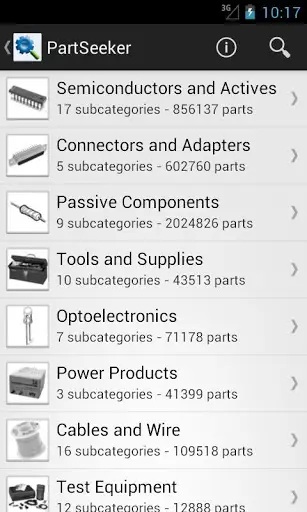
PartSeeker – is an app for searching electronic parts and components. Unfortunately this app is a paid one and the good side is that you can buy it for less than 2 USD. This app is made and released by the same company (IERO) which made ElectroDroid (see above) app. IERO has made this app by using the extensive component library of Octopart (the electronic component search engine). This app comes handy while you are away travelling and is keen to search for a component using your mobile device (may be smart phone or a tab!). 
Best and Free Android Applications for Electronics and Electrical Engineers
PIC Microdatabase - another free app from IERO, which integrates well with ElectroDroid app. This app is nothing more than a database of PIC micro controllers manufactured by Microchip. This app lists all PIC and dsPIC family of controllers in an easy to use user interface. Features and specifications of all controllers along with pinout diagrams of select ones are available. The most attractive feature is a search functionality in which you can search for a controller with particular features you would like to have.As an example you can search for controller from PIC that belongs to a particular PIC family like PIC 10, with specific EPROM values, specific RAM, USB 2.0 or higher, specific internal oscillator values  etc. The app will output all PIC controllers that matches your search criterias. So far more than 10,0000 users have downloaded this application.
Best and Free Android Applications for Electronics and Electrical Engineers
DroidTesla – is another free app for simulating electronic circuits. This SPICE simulation tool is quiet similar to the app “EveryCircuit” mentioned above in its functionality - means you can build and simulate a circuit. But they both (EveryCircuit and DroidTesla) differ in user interface and features provided. I found the free version of “EveryCircuit” much more appealing than DroidTesla. EveryCircuit has certain predefined circuits like halfwave rectifier, inverting amplifier etc which you can simply load to workspace and simulate in realtime. DroidTesla has given a list of examples in their free app version but none of them loads properly to workspace. The reason is most of the example circuits contain a particular component which may be available only on DroidTesla’s commercial version. User interface of  EveryCircuit is much better than that of DroidTesla. DroidTesla’s commercial version might be much better than EveryCircuits premium version, as DroidTesla has large set of component library to choose from. DroidTesla will definitely outshine EveryCircuit – if the number of component libraries available is taken into account. Both of the apps commercial versions are priced competitively. If “user interface” is your primary preference, I will recommend EveryCircuit premium. On the other hand, if number of component library is your first preference, I shall recommend DroidTesla commercial version
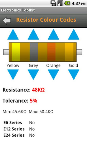
ElectronicsToolKit – is another free app which is a collection of simple tools like resistor color code calculator, series and parallel calculator etc. Almost all those tools are available in ElectroDroid app too, except for a Power Triangle calculator. I have listed this app here as it is free (and I have spent some time to download and test this app in my Galaxy) and you guys can try out, if you have time.More than 10,000 users have tried this application.
Best and Free Android Applications for Electronics and Electrical Engineers
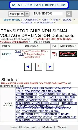
AllDataSheet App – This app is free version of the Datasheet website Alldatasheet.com. This app is nothing more than a book mark to alldatasheet website’s mobile version. I dont recommend you to download this app as your purpose will be served by visiting Alldatasheet.com from your mobile browser (which will get automatically redirected to mobile version) 
EquivalentResistanceSolver – is another free app which helps you to calculate the equivalent resistance of a circuit. This app may not be that useful for a professional as the “user interface” is average. It takes lots of time to build a “Series-Parallel” combination. Might be handy for students who are learning about the concepts for the first time. 
RF Pad Calculator – is a free app that helps to calculate the resistor values required to build an RF attenuator. 
FilterCalc – is another free app from the same developer of Amplicalc, which helps to realize filter design by finding the appropriate values. 
ControlCalc – is yet another free app from the same developer of Amplicalc, which helps in simulating closed and open systems, calculate transfer functions, state response & you can save the output as PNG. 
M32 Assembly – is another interesting application which helps you to learn assembly language by yourself. This app infact is a simulator for the M32 processor.
Electronica – is another app which is open source (the source code of this app is available for free download). This app is also a collection of simple and easy to use tools that comes handy for an every day electronics enthusiast/professional or even a student.   
There are a handful of other free android applications like Ohms Law calculator, 555 Timer Calculator which I have not mentioned here. The reason is simple, most of the “electronics tools“ apps like ElectroDroid, Electronica, ElectronicsToolsKit etc has Ohms Law calculation, Resistor Colourcode calculation and 555 Timer calculator embedded in them!

if u like the post just say thank u in comment box.

[ System Set up ]An android based monitoring and alarm system for patients with chronic obtrusive disease.

Some Importantant links below with reports.just view the link below. if u want any project report just search any project on our search box
Arduino interesting projects:   
Arduino 30 simple and good projects 
Atmega projects lists
Android Electronics projects lists
Rf based Projects with report
engineering study notes 
GSM GPS based projects with report
Bluetooth based projects with reports
System Set up
The following chapter will go step by step through each part of the developed
system, including hardware devices and software involved in the development
process. Everything from the initial set up to the data collection stage is covered.

3.1 Sensors

Sensors as a hardware equipment is an essential part of any monitoring device.
The total amount of sensors involved in a monitoring process can be increased,
providing a more sophisticated level of the analysis and enchanting data processing.
Possible suggestions are discussed in Chapter 4 and 6. It was decided,
however, to use a limited amount of sensors in the current project and establish
a reliable connection for subsequent data transferring.

3.1.1 Accelerometer

The accelerometer sensor is an important component of the developed system
as well as any other system involving patients monitoring. It provides a basic information
about daily activity of the person, which can be further modified and
used as one of the parameters for the analysis. Before describing the accelerometer
application and usage in this particular project we consider it sufficient to
mention several features of this type of sensor.
Conceptually, any accelerometer behaves as a damped mass on a spring.
When the accelerometer experiences an acceleration, the mass is displaced to
the point where the spring is able to accelerate the mass at the same rate as the
casing. The displacement is then measured to give the acceleration.
In commercial devices, piezoelectric, piezoresistive and capacitive components
are commonly used to convert the mechanical motion into an electrical
signal1. Piezoelectric accelerometers rely on piezoceramics (e.g. lead zirconate
1Accelerometer, http://en.wikipedia.org/wiki/Accelerometer
31


Figure 3.1: Accelerometer axes
titanate) or single crystals (e.g. quartz, tourmaline). These crystal structures become
stressed by accelerative forces, which causes a voltage to be generated.
Piezoresistive accelerometers are unmatched in terms of their upper frequency
range, low packaged weight and high temperature range and preferred in high
shock applications. Capacitive accelerometers typically use two silicon micromachined
sensing elements. Having these two micro structures next to each
other, creates a certain capacitance between them. If an accelerative force moves
one of the structures, then the capacitance will change. Additionally, converting
some circuitry from capacitance to voltage we will be able to get a full
accelerometer 2. Performance of these type of sensors is superior in the low frequency
range and they can be operated in servo mode to achieve high stability
and linearity. Modern accelerometers are often based on small electromechanical
devices (micro electro-mechanical systems or MEMS) and normally inbuilt
in the latest generation of the smart phones (including the one involved in the
project). In our case it can be reached by programming through the android
operating system with the help of ”SensorManager“ class and special Sensor
Activity. The simple pseudo code example is provided below:
S e n s o rAc t i v i t y {
g e t S e n s o r S e r v i c e ( ) ;
g e tDe f aul t S ensor ( SensorType ) ;
onResume ( ) {
r e g i s t e r S e n s o r L i s t e n e r ( t h i s , Ac c e l e rome t e r ) ;
}
onPause ( ) {
u n r e g i s t e r S e n s o r L i s t e n e r ( t h i s , Ac c e l e rome t e r ) ;
2A beginner’s guide to accelerometers, http://www.dimensionengineering.com/accelerometers.htm
3.1. SENSORS 33
}
onSensorChanged ( SensorEvent ) {
Do something i f s ensor i s moved ;
}
}
Once the sensor is activated there are several methods provided by the previously
mentioned class which can be used in order to measure activity. It is
represented by three variables x,y,z which output device acceleration along the
raw, pitch and yaw direction[33] (see Figure 3.1). First of all, we need to make
sure at least one sensor is available for the measuring process. A special method
”isSupported“ is used for this purpose:
i sSuppor t ed ( ) {
i f ( notSuppor ted ) {
g e t S y s t emS e r v i c e ( s e n s o r S e r v i c e ) ;
L i s t s ensor s = g e t S e n s o rLi s t ( ac c e l e rome t e rType ) ;
suppor ted = new Boolean ( s e n s o r s S i z e ) ;
} e l s e {
do nothing i f s ensor i s suppor ted ;
}
}
r e turn suppor ted ;
}
The next step is to invoke a special ”startListening“ process which registers
a listener and starts listening to the accelerometer callback for possible events
(shaking, changing position etc.). This method also includes a configuration
component where we can decide on a threshold for the changes in accelerometer
and interval between shakes. It can help to react only on significant changes
and simplify data collection in the next stages.
Now, any change/event, which arises while the accelerometer is in the ”listening
mode” will be registered and processed. It is reasonable to introduce a
threshold for eliminating insignificant changes in raw/pitch/yaw values of the
accelerometer. All the values below this threshold will not be considered. We
can furthermore use previously detected acceleration and display it on a screen
or store it in a file for further processing. Both options are implemented in our
case. Possible approaches for accelerometer data processing will be described
in Chapter 4.

3.1.2 Nonin Wrist 0x2

The following section is dedicated to the technical specifications of the sensor
device used in this project. Description is based on a ”Fingertip Oximeter
Technology Specifications” document [1] and provides additional information
concerning the current system features. The picture of the sensor is provided on


All the technical specification and parameters of the Pulse Oximeter are
combined into an appropriate table (see Figure ??). The most significant information
in terms of the system development are Oxygen Saturation and Pulse
Rate Accuracy.


The table is followed by bluetooth configurations including Operating Frequency
and Operating Range.
Technically, Nonin Wrist 0x2 oximeter is a slave device. To connect sensor
to a master device, the master device must first associate with the 3150 by inquiring
for the 3150. For the initial pairing of a new host device (master) to
the 3150, it is discoverable for a minimum of 2 minutes after power-on. During
the discovery period, the 3150 will broadcast a friendly name to the master.
The name starts with ”Nonin_Medical_Inc._”, followed by a 6-digit number,
referred to as the PIN. The PIN is etched on the back of the 3150 enclosure.


To complete the pairing process once the master (host) device finds the 3150,
the PIN must be provided to the master device. Once paired, the master must
establish the connection to the sensor.
This particular model provides measurements in several different data formats:
• Data format 13 – provides easy spot-check measurements with the storage
and forwarding of measurements.
• Data format 8 – provides real-time oximetry measurements every second.
• Data format 2 – provides real-time oximetry measurements with compressed
waveform (8 bit waveform) every 1/75 of a second.
• Data format 7 – provides real-time oximetry measurements with full resolution
waveform (16 bit waveform) every 1/75 of a second.
For data formats 1, 2, 7 and 8, the 3150 will not initiate the connection using
the attempt to reconnect (ATR) option. If the system has only one COM port
available, data format 2, 7, 8, or 13 should be used with the ATR disabled. The
master device must initiate the connection by occasionally polling for the 3150.
For an automatic wireless reconnection, a software should be designed to periodically
poll for the 3150. If polling for the 3150 is not possible, Bluetooth
connection should be started manually. Because the manual method typically
requires the user to initiate the Bluetooth connection, the seek/polling method
has its advantages.
The 3150 will be discoverable when not paired to an existing master. Any
previous master devices should be off. Once the device pairs and establishes the
Bluetooth connection with the 3150, sensor will automatically send continuous
data to device as defined in Data Format Definition section later. For further details
on establishing a Bluetooth wireless connection see Appendix A. A Bluetooth
connection indicator becomes available on the screen, after pushing and
holding a bluetooth button. Once the Bluetooth connection is established, the
3150 receives and transmits data using the SPP protocol. Additionally, there are
several settings and commands for data format and time information:
 (1) Setthe Data Format and Activation,
 (2) Set Multiple Parameters,
 (3) Set the Date and Time in the 3150,
 (4) Set Bluetooth Radio timeout (power saving feature),
(5) Get the Date and Time from the 3150,
 (6) Get the Serial Number in the3150,
 (7) Get revision number.
In each case user must send a preliminary byte command string in order to
select Data format, set or retrieve time. A data format is a key information for
receiving, displaying and processing the sensor measurements. Thus, it is important
to mention several details on it’s structure. A default Serial Date Format 2
(one of the listed above) was used in development. This data format provides
continuous data transmission of a 5 byte data packet sent 75 times per second.
The data packet includes real-time data of: 8-bit waveform value, beat-to-beat
SpO2 value, SpO2 and Pulse Rates values formatted for both recording and
display purposes, status of the measurement and battery. Each particular byte
represents a valid information.
Byte 1 – START BYTE:
Always set to a 01 value.
Byte 2 – STATUS BYTE:
This byte provides status information at a rate of 1/75 of second.
Range: 128 to 255
Byte 3 – PLETH BYTE:
This byte consists of an 8 bit plethsmographic waveform (pulse waveform).
The pulse oximeter infra-red signal is filtered and then compressed into an 8 bit
value. The compression provides good detail for low to large pulse signals. For
uncompressed waveform refer to Data Format 7.
Range: 00 to 255
Byte 4 – FLOAT BYTE:
This byte is used for SpO2, Pulse Rate, and information that can be processed
at a rate of 1/3 of second.
Range: 00 to 127
When the device is removed from the finger the last SpO2 and Pulse Rate
reading will be reported for 10 seconds before changing to the missing data
value. During this 10 second period the sensor alarm bit (SNSA) is set, indicating
that the finger has been removed. This feature is useful for spot-check
measurements. When SpO2 and HR cannot be computed, the system will send
a missing data indicator. For missing data, the HR equals 511 and the SpO2
equals 127.

Byte 5 – CHK:
This byte is used for the checksum of bytes 1 through 4.
A concrete information on the processing of the sensor measurements can be
found in Chapter 4 of the thesis.

3.2 Processing Device

The current section will go through the second part of system hardware used for
the developing purposes. Several main aspects concerning technical parameters
and programming Android API (Application Programming interface) will be
covered and formulated according to their involvement in the process.
3.2.1 Samsung smart-phones
All the information sent by sensors (excluding accelerometer, inbuilt in phone)
can be received by processing device through Bluetooth connection. Both Samsung
Galaxy S and Samsung Galaxy Tab used for the actual thesis work, have
a Bluetooth functionality. Thus, next step would be to get an access to this feature
through the programming language, which is in our case Java. No license
or special agreement is required to program previously mentioned devices, both
based on an Android operating system.
Before proceeding to the next step, it is important to mention some general
aspects about Bluetooth option. According to the both smart-phones manuals,
Bluetooth is a short-range wireless communications technology capable of exchanging
information over a distance of about 10 m without requiring a physical
connection [36]. Furthermore, we do not need to line up the devices to beam
information with Bluetooth. If devices are within the range of one another, any
information exchange between them is possible even if they are located in different
rooms. However, we should always ensure that sharing and receiving data
is performed with devices that are trusted and properly secured. If there are obstacles
between the devices, the operating distance may be reduced. Moreover,
some devices, especially those that are not tested or approved by Bluetooth SIG
3, may be incompatible with the involved device.
Other than Bluetooth option, there are more technical parameters possessed
by Samsung Galaxy S, making it sufficient enough to be involved in monitoring
system and subsequent data analysis. The parameters within our scope are
memory (capacity) and operating frequency. The Samsung Galaxy S has the
S5PC110 processor. This processor combines a 45 nm 1 GHz ARM Cortex-
A8 based CPU core with a PowerVR SGX 540 GPU made by Imagination
Technologies which supports OpenGL ES 1.1/2.0 and is capable of up to 20
3Special Interest Group, http://www.bluetooth.com/Pages/About-Us.aspx
million triangles per second. The CPU core, code-named ”Hummingbird”, was
co-developed by Samsung and Intrinsity.
In terms of memory, the Samsung Galaxy S has 512 MB of dedicated LPDDR2
RAM (Mobile DDR) and 16-32 MB of OneDRAM. Some variants also come
with either 8GB or 16GB of OneNAND memory combined in a package-onpackage
stack with the processor. An external microSD card slot supports up
to 32GB of additional storage memory 4. Additionally, the smart-phones used
for programming runs on Android 2.1 (a.k.a. ”Eclair”) operating system.

3.2.2 Application development

It was decided to use Eclipse programming environment for development as one
of the most sufficient and user friendly. All the communications between processing
device and sensors are implemented through the application interface.
A special application was designed and successfully ran for this particular purpose.
The first step and a one of the main goals of this program was to establish
a reliable connection. Once connection is initialized and running, it is important
to maintain a signal in order to provide consistent interaction. In other
words, we want to continuously store all the data received from the sensor in
the phone memory and any kind of interruption would negatively affect the
quality of the future analysis. A special android project was created, based on
the Eclipse software in order to use all the available classes of android development
environment. A project consists of two main ”activities” and one special
”service” which is responsible for a consistent data transmission. We consider
it important to highlight main parts of these programming components in the
following description.
Firstly, we want to ensure the Bluetooth option is available and enabled
on the device before we start any kind of operations [27]. Two simple commands
perform a system check for both previously mentioned cases and can be
executed with the following pseudo code:
/ / check i f blue tooth i s suppor ted
i f ( BluetoothAdapter ( notSuppor ted ) ) {
pr intOut ( ’ ’ Blue tooth i s not a v a i l a b l e ’ ’ ) ;
f i n i s h ( ) ;
r e turn ;
}
and
/ / check i f blue tooth i s enabled
i f ( BluetoothAdapter ( notEnabled ) ) {
BluetoothAdapter = Act ionReques tEnable ;
}
The last command sends a request to enable bluetooth on the operating device
in case this option is currently disabled. Once bluetooth function is switched on,
4Samsung Galaxy, http://en.wikipedia.org/wiki/Samsung_Galaxy_S
we can proceed to the next step. An advanced user interface was not among the
highest priorities of this project, however, several options are available within
the main application screen depicted below.
It is important to store some basic patients personal information, which will
be further used in data processing part. So, as it is shown on Figure 3.5, every
user can type in and save his/her age and weight in the corresponding field.
The number will be later written to a special file and ready to be extracted for
processing.
Figure 3.5: Application main screen
Next option allows user to get an access to accelerometer sensor through
the android API. This part was described more specifically in Section 3.1.1 of
this thesis. A data storing procedure is performed again. This time a special
file, representing accelerometer along three axis is created and updated continuously.
Current numbers are displayed on a screen and match the values stored
to the device memory. You can read more about data format in Section 3.2.3
of the current chapter.
After accelerometer is set up and running, we can proceed to the main part,
where connection between a sensor and android phone needs to be established.
A ”START APP” button will initiate a second main activity, which provides
user with a list of paired devices and opportunity to search for new ones (see
Figure 3.6).
In order to create a connection between application and a remote device
(sensor in our case), we must implement either server-side or client-side mechanisms,
because one device must open a server socket and the other one must
initiate the connection (using the server device’s MAC address to initiate a connection).
The server and client are considered connected to each other when
they each have a connected BluetoothSocket on the same RFCOMM channel.
At this point, each device can obtain input and output streams and data trans40

fer can begin. We are interested in client-side option.
So, in order to initiate a connection with a sensor (a device holding an
open server socket), we should first obtain a BluetoothDevice object that represents
the remote device. After that we use the BluetoothDevice to acquire a
BluetoothSocket and initiate the connection. This part of the mechanism is implemented
in a ”BluetoothService” section of the program.
After device is chosen and bluetooth connection service is running, application
will automatically return to a main screen and we can now observe
measurements below the ”Oximeter sensor” section on a display. A step by
step tutorial on starting sensor readings is provided in a special manual (see
Appendix A) written for the Backagården personnel.

3.2.3 Data collection

Once the system is set up properly and the main application has been started
on the testing device, it is possible to start data collection for the subsequent
analysis. Two possible categories of the data that can be processed are represented
by two different scenarios. Firstly, we perform testing with the healthy
person, who is unlikely to have any kind of abnormalities and moreover any
kind of chronic diseases. A second data set is expected to come from preliminary
selected patients, who agreed to participate in the experimental part of
the current research. The experimental part is described in details further below
forming Chapter 5 of the thesis. The process implies receiving, storing and
analyzing the data extracted from the measuring devices. All the information is
sent via Bluetooth channel establishing “mobile phone - sensor” communication.
processing device. Each measurement is retrieved from a different source and
represented by four separate files:
• sensors.txt (pulse rate and oxymetry)
• activity.txt (raw, pitch, yaw from accelerometer)
• age.txt (user input)
• weight.txt (user input)
The first two files have a particular format and consist of three separate column
vectors, including a special time vector.
20110519T175925 82 96
20110519T175927 82 97
20110519T175929 82 96
20110519T175931 82 96
This information is intended to simplify and at the same moment significantly
improve further analysis of the data. Having access to the time makes it easier
to register every particular change and follow the input flow as it is shown on


The entire concept of Chapter 3 was based on several goals announced in
the introduction part of the thesis. Firstly, it was required to establish a reliable
connection between sensor and processing device, which is impossible without
considering key aspects of sensor technical specification such as data format
and operating modes. Secondly, we provide general information on data collection
procedure, which is summarized in Table 3.1 above. Moreover, Table 5.3

T

from Section 5.2 contains detailed information about data transfer, including
data loss in percentage. These measurements are sent and retrieved in a particular
format (see a cutout of measurements above), developed for this particular
application. It was designed to cover all the details and provide user with an
easy interface for a sensor - device communication. The very same application
carries out a data collection procedure.

Some Importantant links below with reports.just view the link below. if u want any project report just search any project on our search box
Arduino interesting projects:   
Arduino 30 simple and good projects 
Atmega projects lists
Android Electronics projects lists
Rf based Projects with report
engineering study notes 
GSM GPS based projects with report
Bluetooth based projects with reports

if u like the post just say thank u in comment box.

[ SOLUTION ] ANDROID phone do not respond

The phone doesn't respond at all


Problem: 

It may happen that your Android phone or Android tablet will not respond at all. This is what once happened to my HTC One X. I ended a call, the phone froze so I waited, waited, waited. The screen turned off and the phone behaved as if it was turned off (but I know it wasn't). In such a situation, we usually remove the battery. But what can we do if there is no battery to remove like in my HTC? :)

Solution: 

When the phone is unresponsive, it's usually a good idea to restart it. You can do that by holding the power button for a few seconds and then tapping Restart phone. This solves the problem in most cases.
Android Problems

You can also remove the battery (if you have one), which always helps. In the case of my HTC, the only thing that worked was to hold the Power button for 10 seconds. After that the phone automatically restarted and everything went back to normal.

[ SOLUTION ] ANDROID Backlight turns on and off on its own

Backlight turns on and off on its own


Problem: I encountered this problem on HTC One X, HTC Desire Z and HTC Desire S. I suppose this doesn't concern HTC phones only. This is not the most serious problem in the world but it can be a bit annoying when your phone, out of the blue, turns the screen on in the middle of the night just to turn it off in a few seconds. I guess it can also significantly reduce the battery life.

Solution: In one phone this Android problem disappeared on its own  as suddenly as it appeared.  In HTC Desire S it was enough to restart the phone (hold the power button for a few seconds and then tap  Restart).

However, in my HTC One X  the problem didn't disappear until  I restored factory settings. To do that,  go to Settings > Backup & reset > Reset Phone. Remember about backup.
Android Problems: Let's reset our Android device.

[ SOLUTION ] ANDROID small popup menu doesn't appear after holding the power button

A small popup menu doesn't appear after holding the power button


Problem:

 This is also one of the most often encountered Android problems. When you hold the power button for a few seconds, a small Phone options menu (like the one on the screenshot) will  or, at least, should appear.

This menu allows you to power off your phone, turn off or on airplane mode or restart your phone. However, in my previous phone (HTC Desire S) at some point this function simply stopped working and the phone wouldn't react to holding the power button.


Solution: 

This Android problem is a real pain in the neck. Unfortunately, restarting the phone or turning it off and on didn't help. The only thing that worked was restoring factory settings.

To do that, do go Settings > Backup & reset > Reset Phone. Before you do that, remember to backup your settings with either a third party app or use the default function also available under Backup & reset > Backup & restore.

If you want to discover some apps for making backup, don't miss  Android backup apps section.
- See more at: http://www.inlovewithandroid.com/android-problems-troubleshooting.html#sthash.PGT7jWTO.dpuf