Showing posts with label WIRELESS. Show all posts

Wireless.Optical.Communication.Systems.Springer.Verlag.Telos

About us
We provide free e-books for download without any registration or money.
Search for any ebook you need in our search box.
Website:engineeringfourum.blogspot.com
Type:Free
Registration: no any
No of ebooks: 7037(total in this blog)
About book
Name : Wireless.Optical.Communication.Systems 
Author: 
Edition: 
Published on:2013-03-16 
File Format: 
Download link: Below
Description:The ebook s the wireless optical communication system.A free download book 
in our web .Search more ebook on our blog to download .
 Size:7MB
Image: 
 
Download Here
 Wireless.Optical.Communication.Systems.Springer.Verlag.Telos.pdf 

[REPORT] Smart phone Android Operated Robot ,WIRELESS,BLUETOOTH


Some Importantant links below with reports.just view the link below. if u want any project report just search any project on our search box
Arduino interesting projects:   
Arduino 30 simple and good projects 
Atmega projects lists
Android Electronics projects lists
Rf based Projects with report
engineering study notes 
GSM GPS based projects with report
Bluetooth based projects with reports


Smart phone Android Operated Robot

The project aims in designing a Robot that can be operated using Android mobile
phone. The controlling of the Robot is done wirelessly through Android smart phone
using the Bluetooth feature present in it. Here in the project the Android smart phone is
used as a remote control for operating the Robot.
Android is a software stack for mobile devices that includes an operating system,
middleware and key applications. Android boasts a healthy array of connectivity options,
including Wi-Fi, Bluetooth, and wireless data over a cellular connection (for example,
GPRS, EDGE (Enhanced Data rates for GSM Evolution), and 3G). Android provides
access to a wide range of useful libraries and tools that can be used to build rich
applications. In addition, Android includes a full set of tools that have been built from the
ground up alongside the platform providing developers with high productivity and deep
insight into their applications.
Bluetooth is an open standard specification for a radio frequency (RF)-based,
short-range connectivity technology that promises to change the face of computing and
wireless communication. It is designed to be an inexpensive, wireless networking system
for all classes of portable devices, such as laptops, PDAs (personal digital assistants), and
mobile phones. It also will enable wireless connections for desktop computers, making
connections between monitors, printers, keyboards, and the CPU cable-free.
The controlling device of the whole system is a Microcontroller. Bluetooth
module, DC motors are interfaced to the Microcontroller. The data received by the
Bluetooth module from Android smart phone is fed as input to the controller. The
controller acts accordingly on the DC motors of the Robot. The robot in the project can
be made to move in all the four directions using the Android phone. The direction of the
robot is indicated using LED indicators of the Robot system. In achieving the task the
controller is loaded with a program written using Embedded ‘C’ language.

U V W Electronics Ebooks

 these are the some pf the electrical and elerctronics ebooks that are included commonley in the sallabus reference books...Do download them and like our page ..thank..if you dond find any book comment in the comment section.


 W
   Wireless.Optical.Communication.Systems.Springer.Verlag.Telos.Sep.2004.ISBN0387227849.pdf                                       2013-03-16 12:05  7.0M  
      Wireless.Networks.First-Step.(2005).chm                                                                                        2013-03-16 12:05  1.2M  
      Wireless.Internet.Telecommunications.Artech.House.Publishers.eBook-YYePG.pdf                                                   2013-03-16 12:05  6.3M  
      Wireless.Foresight.Scenarios.of.the.Mobile.World.in.2015.John.Wiley.and.Sons.eBook-LiB.chm                                     2013-03-12 15:49  2.7M  
      Wireless.Data.Technologies.Reference.Handbook.John.Wiley.and.Sons.pdf                                                          2013-03-12 15:48  2.1M  
      Wireless.Data.Demystified.McGraw.Hill.eBook-LiB.pdf                                                                            2013-03-15 00:38  5.2M  
      Wireless Technology Protocols Standards and Techniques.pdf                                                                     2013-03-15 00:36  5.4M  
      Wireless Mobile Networking with ANSI-41, Second Edition.pdf                                                                    2013-03-09 15:26  2.0M  
      Wireless Communications.pdf                                                                                                    2013-03-09 14:22  2.6M  
      Wireless Communication Technology.pdf                                                                                          2013-03-13 08:25   12M  
     Ultrasound Imaging Technologies.pdf                                                                                        2013-03-13 08:25  5.9M  
      Wireless Communication Systems - Prentice Hall PTR.chm                                                                         2013-03-13 08:28   12M  
      Wiley - Essentials of Financial Analysis.pdf                                                                                   2013-03-13 06:02  1.8M  
      Wiley - Digital Image Processing WK Pratt - Third Edition(2001).pdf                                                            2013-03-13 07:30   17M  
      Wiley - Data Networks, IP and the Internet - Protocols, Design and Operation.pdf                                               2013-03-17 15:07   10M  
      Wideband.TDD.WCDMA.for.the.Unpaired.Spectrum.John.Wiley.Sons.May.2005.eBook-LinG.pdf                                           2013-03-13 06:12  4.5M  
      WCDMA Mobile Communications System.pdf                                                                                         2013-03-13 06:12  3.9M  
      Wavelets, with applications in signal and image processing  Bultheel A. (2002)(T)(181s).djvu                                   2013-03-08 23:37  1.3M  
      Wavelets For Kids B.ps                                                                                                         2013-03-08 23:37  264K  
      Wavelets For Kids A.ps                                                                                                         2013-03-08 23:37  1.0M  
      Waveguide Handbook.pdf                                                                                                         2013-03-13 09:01   19M  
      W-CDMA_and_cdma2000_for_3G_Mobile_Networks.pdf 
 
V  
      Voice Over 802.11.pdf                                                                                                          2013-03-13 05:58  1.9M  
      Video.Data.Management.and.Information.Retrieval.IRM.eBook-YYePG.pdf                                                            2013-03-13 05:58   13M  
      Video Processing and Communications.pdf                                                                                        2013-03-17 11:12   17M  
      Video Demystified A Handbook For The Digital Engineer.pdf 
 U
 
      US Navy - Digital Data Systems.pdf                                                                                             2013-03-16 17:37   16M  
      Understanding Telephone Electronics.pdf                                                                                        2013-03-17 08:05   12M  
      Understanding Optical Communications.pdf                                                                                       2013-03-17 08:04  5.2M  
      Understanding Microwaves (Scott).pdf                                                                                           2013-03-15 02:43   15M  
      Understanding Digital Terrestrial Broadcasting_MAZ - Artech House.pdf                                                          2013-03-13 07:58  1.3M  
      Understanding Data Communications.pdf                                                                                          2013-03-13 07:58  9.6M  
      Understanding Cellular Radio.pdf                                                                                               2013-03-09 16:01  732K  
      Ultrasound Imaging Using Coded Signals.pdf                                                                                     2013-03-09 20:07   12M  
     

if u like the post just say thank u in comment box.

[ ARDUINO ] XBee Wireless Accelerometer


XBee ZNet 2.5 Wireless Accelerometer

I managed to put together a wireless accelerometer the other night using my two new XBees, an Arduino XBee shield, an XBee Explorer USB, an ADXL330, and some Python. I struggled a bit with some of it, so here's what I learned:

First, a parts list.
I'm not sure exactly what the specs are on the XBee that comes with the Arduino shield. But, it is definitely a series 2.5.

The first thing to do is to configure and upgrade the firmware on your XBees. To do that, you'll need X-CTU (for the firmware upgrade at least, but it's also nice for configuration) which, unfortunately, is only available for Windows. But, it works fine from VMware. First up, the XBee we'll hook up to the computer to read incoming data from the accelerometer:
  • Plug one of the XBees into the Explorer (it's also possible to do this from the Arduino shield by shifting the two XBee/USB jumpers to USB and removing the MCU) and plug it into your USB port.
  • Crank up X-CTU, select the appropriate USB communications port (com port), click "Modem Configuration" and then "Read." This will determine what XBee is connected and what firmware is on the device.
  • Select "Always update firmware."
  • Click "Download new versions..."
  • Select the latest version of ZNet 2.5 Router/End Device API. The API version is necessary in order to read the incoming data on the computer. Only API firmware will write incoming sensor data to the device's UART so it can be read over USB/serial.
  • Click "Write." You may get an error after the writing is complete. That's normal. It's because you've changed the way the XBee communicates over it's UART. Go back to the "PC Settings" tab, select "Enable API" and then click "Read" on the "Modem Configuration" tab again.
  • Under "Networking," change NI (Node Identifer) to something like "ARDUINO". I named mine Arduino because I used the Arduino and XBee shield to provide a USB connection to the computer.
  • Click "Write" and hook it up to your computer. This is the XBee that your accelerometer will be sending data to. We'll hack up some Python to read that data later.
Next up is the XBee we'll hook to the accelerometer:
  • Follow the same steps as before until you reach the firmware selection.
  • Select the latest version of ZNet 2.5 Router/End Device AT.
  • Under "Networking," change NI (Node Identifer) to something like "ACCELEROMETER".
  • Under "I/O Settings," change D0-D2 to 2-ADC. These pins will be used to read from the accelerometer.
  • Again under "I/O Settings," change IR (sample rate) to 1F4 (hex for 500 milliseconds).
  • Click "Write."
  • Go to the "Termainal" tab. To enter command mode on the XBee, send it "+++" (do not press enter). It will respond with "OK". Next type "ATDNARDUINO" (or whatever you called your other XBee). That will set the destination node to your other XBee. It should respond with "OK". Next, send it "ATWR". That will write the settings to memory so that they aren't lost when the XBee is powered off.
    +++OK
    ATDNARDUINO
    OK
    ATWR
    OK
  • Finally, hook up your XBee and ADXL330. You can power both with 3.3V (3V works too). Unfortunately, the XBee 2.5 series ADCs only accept voltages in the range of 0-1.2V. To get better results, you'll need to add voltage dividers on the X, Y, and Z axes. I don't have those in the schematic. If you use 3V, it works well enough to detect motion. For finer mesurements, you'll need the dividers.


Now, you should be able to test that everything is working. Connect to the Arduino XBee with the X-CTU terminal. Assuming your accelerometer XBee is powered on, you should see lots of data flying by. The data is transmitted in API packets over the XBee's UART, to the FTDI chip, to your computer's USB-serial device. The API packet specification is in the XBee 2.5 manual. Here's some Python that does part of the decoding.
import xbee
 Although there is a XBee Python library, it doesn't currently support series 2.5 modules.
import serial  # pySerial
import struct
import sys

THRESHOLD = 5

tty = sys.argv[1]

s = serial.Serial(tty, 9600)
movement = None
while True:
if s.read() == chr(0x7e):  # Packet start indicator.
  length, api_id = struct.unpack('>Hc', s.read(3))
  if api_id == chr(0x92):  # IO packet type.
    # Lots of bytes we don't care about followed by 3 shorts.
    z, y, x = struct.unpack('>xxxxxxxxxxxxxxxHHH',
                            s.read(length - 1))
    print z, y, x
    if (movement is not None and
        abs(z + y + x - movement) > THRESHOLD):
      print 'You moved!'
    movement = z + y + x
If you read the spec for API packets, you'll notice I'm glossing over a lot of details. The analog IO bytes are always at the end of the packet. Since we enabled only 3 ADCs, we can just grab the last three shorts.

Finally, here is a picture of my breadboarded version (with voltage dividers) of this. It works great. I'm currently working on a PCB so that the whole thing is compact enough to be wearable.


Some further notes:
  • The chip antenna versions are pretty directional. There's a lot of interference in my apartment (a long story for another post) and I don't get very good range. I plan to buy some more 60mW XBee Pros with wire antennas in the future. I'd recommend getting the high power ones unless you're really concerned about battery life. I wish I had.
  • Digi's tech support is really pretty great. I had some trouble flashing one of my XBee's and they got in contact with me on the same business day.
  • Unfortunately, the XBee only has 4 ADCs. If it had one more, you could add a pitch and roll gyro to the mix without an additional MCU. Oh, well.
  • The XBee pin spacing doesn't match standard breadboards. But, the XBee Explorer USB doubles as an XBee breakout board for breadboard designs (as seen in the photo above) if you solder on some additional headers.
if u like the post just say thank u in comment box.

Wireless Networks

 click here complete Lecture Notes: Computer Networks

Wireless Networks

Introduction

As the need of communication became more and more demanding, new technologies in the field of networks developed. One of them is the use of wireless networks. It is the transmission of data from source to destination without the use of wires as the physical media.

Why to use Wireless?

Three reasons may be stated for the over-growing use of wireless networks across the world:
  1. They are ubiquitous networks. As the do not require messy wires as a medium of communication, they can be used to connect far-off places.
  2. They are cheaper than wired networks specially in the case of long-distance communication.
  3. They are pretty effective and fast, especially with the modern advancements in this field.

Some Terms and Technologies:

Transport Layer Protocol

Transport Layer Protocol

What is TCP?

TCP was specifically designed to provide a reliable end to end byte stream over an unreliable internetwork. Each machine supporting TCP has a TCP transport entity either a user process or part of the kernel that manages TCP streams and interface to IP layer. A TCP entity accepts user data streams from local processes, breaks them up into pieces not exceeding 64KB and sends each piece as a separate IP datagram. Client Server mechanism is not necessary for TCP to behave properly.
The IP layer gives no guarantee that datagram will be delivered properly, so it is up to TCP to timeout and retransmit, if needed. Duplicate, lost and out of sequence packets are handled using the sequence number, acknowledgements, retransmission, timers, etc to provide a reliable service. Connection is a must for this service.Bit errors are taken care of by the CRC checksum. One difference from usual sequence numbering is that each byte is given a number instead of each packet. This is done so that at the time of transmission in case of loss, data of many small packets can be combined together to get a larger packet, and hence smaller overhead.
TCP connection is a duplex connection. That means there is no difference between two sides once the connection is established.

TCP Connection establishment

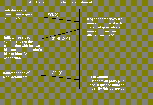
The "three-way handshake" is the procedure used to establish a connection. This procedure normally is initiated by one TCP and responded to by another TCP. The procedure also works if two TCP simultaneously initiate the procedure. When simultaneous attempt occurs, each TCP receives a "SYN" segment which carries no acknowledgment after it has sent a "SYN". Of course, the arrival of an old duplicate "SYN" segment can potentially make it appear, to the recipient, that a simultaneous connection initiation is in progress. Proper use of "reset" segments can disambiguate these cases.
The three-way handshake reduces the possibility of false connections. It is the implementation of a trade-off between memory and messages to provide information for this checking.
The simplest three-way handshake is shown in figure below. The figures should be interpreted in the following way. Each line is numbered for reference purposes. Right arrows (-->) indicate departure of a TCP segment from TCP A to TCP B, or arrival of a segment at B from A. Left arrows (<--), indicate the reverse. Ellipsis (...) indicates a segment which is still in the network (delayed). TCP states represent the state AFTER the departure or arrival of the segment (whose contents are shown in the center of each line). Segment contents are shown in abbreviated form, with sequence number, control flags, and ACK field. Other fields such as window, addresses, lengths, and text have been left out in the interest of clarity.

      TCP A                                                TCP B

  1.  CLOSED                                               LISTEN

  2.  SYN-SENT    --> <SEQ=100><CTL=SYN>               --> SYN-RECEIVED

  3.  ESTABLISHED <-- <SEQ=300><ACK=101><CTL=SYN,ACK>  <-- SYN-RECEIVED

  4.  ESTABLISHED --> <SEQ=101><ACK=301><CTL=ACK>       --> ESTABLISHED

  5.  ESTABLISHED --> <SEQ=101><ACK=301><CTL=ACK><DATA> --> ESTABLISHED

          Basic 3-Way Handshake for Connection Synchronisation
In line 2 of above figure, TCP A begins by sending a SYN segment indicating that it will use sequence numbers starting with sequence number 100. In line 3, TCP B sends a SYN and acknowledges the SYN it received from TCP A. Note that the acknowledgment field indicates TCP B is now expecting to hear sequence 101, acknowledging the SYN which occupied sequence 100.
At line 4, TCP A responds with an empty segment containing an ACK for TCP B's SYN; and in line 5, TCP A sends some data. Note that the sequence number of the segment in line 5 is the same as in line 4 because the ACK does not occupy sequence number space (if it did, we would wind up ACKing ACK's!).

Simultaneous initiation is only slightly more complex, as is shown in figure below. Each TCP cycles from CLOSED to SYN-SENT to SYN-RECEIVED to ESTABLISHED.

      TCP A                                            TCP B

  1.  CLOSED                                           CLOSED

  2.  SYN-SENT     --> <SEQ=100><CTL=SYN>              ...

  3.  SYN-RECEIVED <-- <SEQ=300><CTL=SYN>              <-- SYN-SENT

  4.               ... <SEQ=100><CTL=SYN>              --> SYN-RECEIVED

  5.  SYN-RECEIVED --> <SEQ=100><ACK=301><CTL=SYN,ACK> ...

  6.  ESTABLISHED  <-- <SEQ=300><ACK=101><CTL=SYN,ACK> <-- SYN-RECEIVED

  7.               ... <SEQ=101><ACK=301><CTL=ACK>     --> ESTABLISHED

                Simultaneous Connection Synchronisation
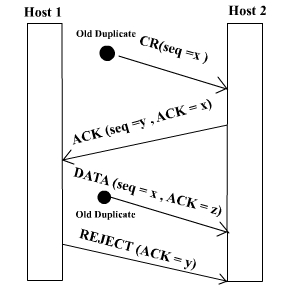
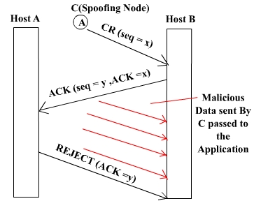
Question: Why is three-way handshake needed? What is the problem if we send only two packets and consider the connection established? What will be the problem from application's point of view? Will the packets be delivered to the wrong application?
Problem regarding 2-way handshake
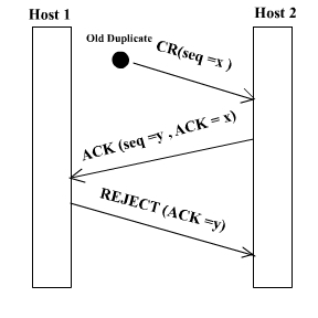
The only real problem with a 2-way handshake is that duplicate packets from a previous connection( which has been closed) between the two nodes might still be floating on the network. After a SYN has been sent to the responder, it might receive a duplicate packet of a previous connection and it would regard it as a packet from the current connection which would be undesirable.
Again spoofing is another issue of concern if a two way handshake is used.Suppose there is a node C which sends connection request to B saying that it is A.Now B sends an ACK to A which it rejects & asks B to close connection.Beteween these two events C can send a lot of packets which will be delievered to the application..

The first two figures show how a three way handshake deals with problems of duplicate/delayed connection requests and duplicate/delayed connection acknowledgements in the network.The third figure highlights the problem of spoofing associated with a two way handshake. Some Conventions
1. The ACK contains 'x+1' if the sequence number received is 'x'.
2. If 'ISN' is the sequence number of the connection packet then 1st data packet has the seq number 'ISN+1'
3. Seq numbers are 32 bit.They are byte seq number(every byte has a seq number).With a packet 1st seq number and length of the packet is sent.
4. Acknowlegements are cummulative.
5. Acknowledgements have a seq number of their own but with a length 0.So the next data packet have the seq number same as ACK.

Connection Establish
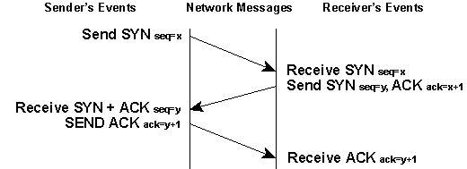
  • The sender sends a SYN packet with serquence numvber say 'x'.
  • The receiver on receiving SYN packet responds with SYN packet with sequence number 'y' and ACK with seq number 'x+1'
  • On receiving both SYN and ACK packet, the sender responds with ACK packet with seq number 'y+1'
  • The receiver when receives ACK packet, initiates the connection.
Connection Release
  • The initiator sends a FIN with the current sequence and acknowledgement number.
  • The responder on receiving this informs the application program that it will receive no more data and sends an acknowledgement of the packet. The connection is now closed from one side.
  • Now the responder will follow similar steps to close the connection from its side. Once this is done the connection will be fully closed.


Transport Layer Protocol (continued)

TCP connection is a duplex connection. That means there is no difference between two sides once the connection is established.
Salient Features of TCP
  • Piggybacking of acknowledments:The ACK for the last received packet need not be sent as a new packet, but gets a free ride on the next outgoing data frame(using the ACK field in the frame header). The technique is temporarily delaying outgoing ACKs so that they can be hooked on the next outgoing data frame is known as piggybacking. But ACK can't be delayed for a long time if receiver(of the packet to be acknowledged) does not have any data to send.
  • Flow and congestion control:TCP takes care of flow control by ensuring that both ends have enough resources and both can handle the speed of data transfer of each other so that none of them gets overloaded with data. The term congestion control is used in almost the same context except that resources and speed of each router is also taken care of. The main concern is network resources in the latter case.
  • Multiplexing / Demultiplexing: Many application can be sending/receiving data at the same time. Data from all of them has to be multiplexed together. On receiving some data from lower layer, TCP has to decide which application is the recipient. This is called demultiplexing. TCP uses the concept of port number to do this.

TCP segment header:
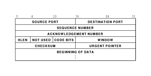
Explanation of header fields:
  • Source and destination port :These fields identify the local endpoint of the connection. Each host may decide for itself how to allocate its own ports starting at 1024. The source and destination socket numbers together identify the connection.
  • Sequence and ACK number : This field is used to give a sequence number to each and every byte transferred. This has an advantage over giving the sequence numbers to every packet because data of many small packets can be combined into one at the time of retransmission, if needed. The ACK signifies the next byte expected from the source and not the last byte received. The ACKs are cumulative instead of selective.Sequence number space is as large as 32-bit although 17 bits would have been enough if the packets were delivered in order. If packets reach in order, then according to the following formula:
    (sender's window size) + (receiver's window size) < (sequence number space)

    the sequence number space should be 17-bits. But packets may take different routes and reach out of order. So, we need a larger sequence number space. And for optimisation, this is 32-bits.
  • Header length :This field tells how many 32-bit words are contained in the TCP header. This is needed because the options field is of variable length.
  • Flags : There are six one-bit flags.
    1. URG : This bit indicates whether the urgent pointer field in this packet is being used.
    2. ACK :This bit is set to indicate the ACK number field in this packet is valid.
    3. PSH : This bit indicates PUSHed data. The receiver is requested to deliver the data to the application upon arrival and not buffer it until a full buffer has been received.
    4. RST : This flag is used to reset a connection that has become confused due to a host crash or some other reason.It is also used to reject an invalid segment or refuse an attempt to open a connection. This causes an abrupt end to the connection, if it existed.
    5. SYN : This bit is used to establish connections. The connection request(1st packet in 3-way handshake) has SYN=1 and ACK=0. The connection reply (2nd packet in 3-way handshake) has SYN=1 and ACK=1.
    6. FIN : This bit is used to release a connection. It specifies that the sender has no more fresh data to transmit. However, it will retransmit any lost or delayed packet. Also, it will continue to receive data from other side. Since SYN and FIN packets have to be acknowledged, they must have a sequence number even if they do not contain any data.
  • Window Size : Flow control in TCP is handled using a variable-size sliding window. The Window Size field tells how many bytes may be sent starting at the byte acknowledged. Sender can send the bytes with sequence number between (ACK#) to (ACK# + window size - 1) A window size of zero is legal and says that the bytes up to and including ACK# -1 have been received, but the receiver would like no more data for the moment. Permission to send can be granted later by sending a segment with the same ACK number and a nonzero Window Size field.
  • Checksum : This is provided for extreme reliability. It checksums the header, the data, and the conceptual pseudoheader. The pseudoheader contains the 32-bit IP address of the source and destination machines, the protocol number for TCP(6), and the byte count for the TCP segment (including the header).Including the pseudoheader in TCP checksum computation helps detect misdelivered packets, but doing so violates the protocol hierarchy since the IP addresses in it belong to the IP layer, not the TCP layer.
  • Urgent Pointer : Indicates a byte offset from the current sequence number at which urgent data are to be found. Urgent data continues till the end of the segment. This is not used in practice. The same effect can be had by using two TCP connections, one for transferring urgent data.
  • Options : Provides a way to add extra facilities not covered by the regular header. eg,
    • Maximum TCP payload that sender is willing to handle. The maximum size of segment is called MSS (Maximum Segment Size). At the time of handshake, both parties inform each other about their capacity. Minimum of the two is honoured. This information is sent in the options of the SYN packets of the three way handshake.
    • Window scale option can be used to increase the window size. It can be specified by telling the receiver that the window size should be interpreted by shifting it left by specified number of bits. This header option allows window size up to 230.
  • Data : This can be of variable size. TCP knows its size by looking at the IP size header.

Topics to be Discussed relating TCP

  1. Maximum Segment Size : It refers to the maximum size of segment ( MSS ) that is acceptable to both ends of the connection. TCP negotiates for MSS using OPTION field. In Internet environment MSS is to be selected optimally. An arbitrarily small segment size will result in poor bandwith utilization since Data to Overhead ratio remains low. On the other hand extremely large segment size will necessitate large IP Datagrams which require fragmentation. As there are finite chances of a fragment getting lost, segment size above "fragmentation threshold " decrease the Throughput. Theoretically an optimum segment size is the size that results in largest IP Datagram, which do not require fragmentation anywhere enroute from source to destination. However it is very difficult to find such an optimum segmet size. In system V a simple technique is used to identify MSS. If H1 and H2 are on the same network use MSS=1024. If on different networks then MSS=5000.
  2. Flow Control : TCP uses Sliding Window mechanism at octet level. The window size can be variable over time. This is achieved by utilizing the concept of "Window Advertisement" based on :
    1. Buffer availabilty at the receiver
    2. Network conditions ( traffic load etc.)
    In the former case receiver varies its window size depending upon the space available in its buffers. The window is referred as RECEIVE WINDOW (Recv_Win). When receiver buffer begin to fill it advertises a small Recv_Win so that the sender does'nt send more data than it can accept. If all buffers are full receiver sends a "Zero" size advertisement. It stops all transmission. When buffers become available receiver advertises a Non Zero widow to resume retransmission. The sender also periodically probes the "Zero" window to avoid any deadlock if the Non Zero Window advertisement from receiver is lost. The Variable size Recv_Win provides efficient end to end flow control.
    The second case arises when some intermediate node ( e.g. a router ) controls the source to reduce transmission rate. Here another window referred as COGESTION WINDOW (C_Win) is utilized. Advertisement of C_Win helps to check and avoid congestion.
  3. Congestion Control : Congestion is a condition of severe delay caused by an overload of datagrams at any intermediate node on the Internet. If unchecked it may feed on itself and finally the node may start dropping arriving datagrams.This can further aggravate congestion in the network resulting in congestion collapse. TCP uses two techniques to check congestion.
    1. Slow Start : At the time of start of a connection no information about network conditios is available. A Recv_Win size can be agreed upon however C_Win size is not known. Any arbitrary C_Win size can not be used because it may lead to congestion. TCP acts as if the window size is equal to the minimum of ( Recv_Win & C_Win). So following algorithm is used.
      1. Recv_Win=X
      2. SET C_Win=1
      3. for every ACK received C_Win++
    2. Multiplicative decrease : This scheme is used when congestion is encountered ( ie. when a segment is lost ). It works as follows. Reduce the congestion window by half if a segment is lost and exponentially backoff the timer ( double it ) for the segments within the reduced window. If the next segment also gets lost continue the above process. For successive losses this scheme reduces traffic into the connection exponentially thus allowing the intermediate nodes to clear their queues. Once congestion ends SLOW START is used to scale up the transmission.
  4. Congestion Avoidance : This procedure is used at the onset of congestion to minimize its effect on the network. When transmission is to be scaled up it should be done in such a way that it does'nt lead to congestion again. Following algorithm is used .
    1. At loss of a segment SET C_Win=1
    2. SET SLOW START THRESHOLD (SST) = Send_Win / 2
    3. Send segment
    4. If ACK Received, C_Win++ till C_Win <= SST
    5. else for each ACK C_Win += 1 / C_Win
  5. Time out and Retransmission : Following two schemes are used :
    1. Fast Retransmit
    2. Fast Recovery
    When a source sends a segment TCP sets a timer. If this value is set too low it will result in many unnecessary treransmissions. If set too high it results in wastage of banwidth and hence lower throughput. In Fast Retransmit scheme the timer value is set fairly higher than the RTT. The sender can therefore detect segment loss before the timer expires. This scheme presumes that the sender will get repeated ACK for a lost packet.
  6. Round Trip Time (RTT) : In Internet environment the segments may travel across different intermediate networks and through multiple routers. The networks and routers may have different delays, which may vary over time. The RTT therefore is also variable. It makes difficult to set timers. TCP allows varying timers by using an adaptive retransmission algorithm. It works as follows.
    1. Note the time (t1) when a segment is sent and the time (t2) when its ACK is received.
    2. Compute RTT(sample) = (t 2 - t 1 )
    3. Again Compute RTT(new) for next segment.
    4. Compute Average RTT by weighted average of old and new values of RTT
    5. RTT(est) = a *RTT(old) + (1-a) * RTT (new) where 0 < a < 1
      A high value of 'a' makes the estimated RTT insensitive to changes that last for a short time and RTT relies on the history of the network. A low value makes it sensitive to current state of the network. A typical value of 'a' is 0.75
    6. Compute Time Out = b * RTT(est) where b> 1
      A low value of 'b' will ensure quick detection of a packet loss. Any small delay will however cause unnecessary retransmission. A typical value of 'b' is kept at .2

Image References

  • http://plato.acadiau.ca/courses/comp/Eberbach/comp4343/lectures/transport/Com-TCP/f20_6.gif
if u like the post just say thank u in comment box.

[Snapshots] wireless controlled robotic arm

 Snapshots   wireless controlled robotic arm


if u like the post just say thank u in comment box.
[CIRCUIT DIAGRAM] WIRELESS CONTROLLED ROBOTIC ARM

CIRCUIT DIAGRAM   WIRELESS CONTROLLED ROBOTIC ARM

i
if u like the post just say thank u in comment box.
[REFERENCE] WIRELESS CONTROLLED ROBOTIC ARM


REFERENCE WIRELESS CONTROLLED ROBOTIC ARM

[1]  B. Pokhrel and group , "Wireless Control Robot" Final Year Project Report,

       Himalaya College of Engineering, Kathmandu, 2067.

[2]S. Sedra and J. Smith, Microelectronic Circuits, London: Oxford University Press, 1998.

[3]"Electronics For U," 10 August 1990. [Online]. Available: http://www.electronicsforu.com. [Accessed 18 Jan 2013].

[4]  M.Banzi,“Getting Started with Arduino”, Oreilly.USA,2008

[5]  “Robotic Arm.” 15 May 1994.[online] Available:. http://jjshortcut.wordpress.com

        [Accessed 13 Feb 2013]

[FINALES] Wireless controlled robotic arm

 5. FINALES

5.1  FUTURE ENHANCEMENT

           The concept principle and methodology that we have used to develop our project can be further developed to build large scale project. It can be advanced further to use in remote sensing approach. Such as in remote sensing in geology, GIS, agriculture etc. similarly it can be developed further and may use in bomb disposal, it can be used in antiterrorist campaign.

The project we have developed is just a prototype. It can be further enhanced by using advanced components and some more concepts. Some of the possible applicable areas might be at:

·                     Remote Sensing

·                     Geographical information system

·                     More easier and helpful tool for disabled and elderly people

·                     Telemedicine in more effective way

·                     Bomb disposal

·                     Radioactive areas

·                     Rural areas development like crop monitoring, irrigation etc

[ INTRODUCTION ] WIRELESS CONTROLLED ROBOTIC ARM

 1. INTRODUCTION

1.1 BACKGROUND


The concept of robots or robot-like automates can be traced back to medieval times. Although people of that era didn’t have a term to describe what we would eventually call a robot they were nevertheless imagining mechanisms that could perform human-like tasks. The robot really became a popular concept during the late 1950’s and early 1960’s. With the automotive industry in full expansion at that time, industrial robots were employed to help factory operators.

The entire world is experiencing the burgeoning interest in the field of technology. Considering the revolutionary development on the robotic world we themed our project on robot control. Being the member of engineering society we play a vital role in changing the society according to the time and need, and hence to make life easier we forward this project. This project is not an original invention we made. At different times in the past, we believe several attempts were made by others on the theme of Robots. But we have used our theoretical knowledge of various electronic components to implement practically in the real world and proud to forward this project on our research, study and effort under the supervision of the supervisor.

[ Source code ]BLUETOOTH CONTROLLED SOLAR POWERED ROBOT VEHICLE


10.2 Source Code

BLUETOOTH CONTROLLED SOLAR POWERED  ROBOT VEHICLE

# define F_CPU 8000000UL
#include <avr/io.h>
#include <util/delay.h>
unsigned char rx_char();
void tx_char (unsigned char);
static unsigned char b;
int main()
{
DDRA = 0X00;
PORTA = 0XFF;
DDRB = 0XFF;
PORTB = 0X00;
DDRC = 0XFF;
PORTC = 0X38; //Turn ON the BUZZER for 1sec & Turn OFF the both LED's
_delay_ms (1000);
PORTC = 0X00; // Turn ON the both LED's for 1sec & Turn OFF the BUZZER
_delay_ms (1000);
PORTC = 0X30; // Turn OFF the BUZZER & both LED's
// UART_init...
UBRRL = 51;
UBRRH = 0;
UCSRB = 0X18;
UCSRC = 0X86;
_delay_ms(125);
While (1)
40
{
unsigned char I;
I= rx_char ();
Switch (I)
{
case 'F':
case 'f': PORTC = 0X30;
while ( (UCSRA & 0X80) == 0X80)
{
unsigned char a;
a = (PINA & 0X01);
if (a == 0x00)
{
if (b == 0x00)
{
PORTB = 0X06;
PORTC = 0X20;
_delay_ms (1000);
PORTC = 0X30;
b = 0x01;
}
else
{
PORTB = 0X09;
PORTC = 0X10;
_delay_ms (1000);
41
PORTC = 0X30;
b = 0x00;
}
}
else
{
while ( (a == 0x01) && ((UCSRA & 0X80) == 0X80) )
{
PORTB = 0X05;
}
}
}
break;
case 'B':
case 'b': PORTB = 0X0A;
PORTC = 0X38;
break;
case 'R':
case 'r': PORTB = 0X06;
PORTC = 0X20;
break;
case 'L':
case 'l': PORTB = 0X09;
PORTC = 0X10;
break;
case 'S':
42
case ’s’: PORTC = 0X30;
PORTB = 0X00;
break;
default: PORTB = 0X00;
PORTC = 0X30;
}
}
}
unsigned char rx_char()
{
while((UCSRA&0X80)==0X00);
return(UDR);
}
void tx_char(unsigned char data)
{
while((UCSRA&0X20)==0X00);
UDR=data;
}
if u like the post just say thank u in comment box.
RF BASED PROJECTS


 RF BASED PROJECTS   :REPORT ARE SHORTLY COMING


  1.     DECRYPTION USING RF COMMUNICATION
  2.     SMS TRANSMITTING USING RF MODULE:> REport
  3.     RF Control Of Induction Stepper Motors and other industrial Loads
  4.     Industrial Automation System Using RF
  5.     CHANNEL RF BASED REMOTE CONTROL
  6.     Remote Areas Data Acquisation Using RF Module Abstract.
  7.     Remote Areas Data Acquisation Using RF Module Abstract.
  8.     WIRELESS CHATTING USING RF Abstract
  9.     Modern house automation (AC/DC) using RF communication Abstract
  10.     Wireless Vehicle trace using IF and IR project Abstract
  11.     DETECTING THE CONDITIONS OF REMOTE AREAS USING RF MODULE
  12.     TRACKING POLICE MAN USING RF PROXIMITY CARD
13.   NOTICE BOARD USING RF MODULE:> REport
like the post just say thank u in comment box.
2. Background :MHSS)

2. Background - MHSS

2.1. GSM/GPRS Based Security System

Based on the IEEE802.11 standard, wireless home network is known as WiFi, which provides a medium for transferring media files [1]. However, it is high cost and high
International Journal of Smart Homepower consumption. Y. Zhao [2] has developed a low cost GSM/GPRS based wireless home security system which includes wireless security sensor nodes and a GSM/GPRS gateway [2-3]. It has the following features:
 (a) low cost, 
(b) low power consumption,
 (c) simple installation,
 (d) fast response and 
(e) simple user interface.
 In general, GSM modem acts as the interface between the users and the sensors nodes. There are 3 types of sensor nodes applied in the system which include the door security nodes, infrared sensor nodes, and fire alarm nodes. This architecture includes components such as filters, amplifiers, analog to digital converters and communication interfaces. The system used a wireless transceiver module to transfer data between gateway and sensor nodes. Every sensor node comprises a microprocessor and a wireless transceiver module. The function of the microprocessor is to receive and analyze the signal from the sensors’ node as well as the current status of the nodes. This system also consists of a sleep timer and switch mode pump circuit, which reduces of the power consumption.
C.K. Ng [4] has developed a wireless security system where an alarm system is programmed in a graphical user interface (GUI). The system is used to monitor the RFID reader, RFID tag and the GSM terminal. The information obtained from the tag is sent to the server in a RF link that is exhibited in a GUI. If the laptop is stolen from the covered region, the alarm system will start to draw attention. Meanwhile, the laptop owner will be notified by an alert message. In addition, the alarm system will not be stopped until the laptop is put back in the covered region, or the program is stopped/terminated.RFID have been available for many years for reading bar codes RFID tag located several meters away [5-8]. It is increasingly being used in other applications ranging from inventory management to anti-counterfeiting protection. In a wireless security system (WSS) [8], a RFID tag is attached to the laptop and RFID reader is connected to server. If the laptop is stolen from the reader, the alarm system will be triggered to draw attention with loud noise. The laptop owner will be notified with short messaging service (SMS) from the server via GSM module system in a few seconds. Alternatively, it can be improved with Bluetooth technology which is embedded in most of mobile laptop today [9]. The GSM terminal is used as the SMS interface to send messages 
[10]. Generally the notebook acts as the base station to run the program. Usually GSM terminal comes with a RS232 connector to external terminal equipment, and the Subscriber Identity Module (SIM) cardholder and the external connector [4].Nakrop Jinaporn [11] has developed a security system against asset theft by using radio frequency identification technology. 
The system consists of five main parts: 
(a) RFID reader and tag,
 (b) GUI,
 (c) database system,
 (d) CCTV and 
(e) wireless transmitter and receiver. 
The RFID reader is installed at the entrance of the campus and the tags are attached on/in student ID cards and their properties. The program of the developed system has the capabilities of investigating the identification process, database management and controlling function of the hardware.GUI is used in a vehicle security system where the information is controlled via the GUI [11-12]. The system is activated when the tag is read while the motorcycle is being located within the effective range. The system will automatically record this incident and exhibit the information on the monitor. Any theft occurrence will turn the monitor on automatically with the alarm signal which alerts other systems. When the burglar occurs, the CCTV will also be started for recording is immediately. The motorcycle engine is shut off automatically when the asset theft occurs however this requires a further investigation.