Showing posts with label robot. Show all posts

Proposal &report Computer Controlled wireless wired Robot

Building a computer controlled wireless robot

  As we always concern on the  cheapest and easiest way to control electronic devices wirelessly using a computer.  For example, you could build a radio controlled relay board, and control it from your computer. You could even control the board with a "small" computer such as an Arduino . If your Arduino has an Ethernet shield, you could use it as a Web server and control your relay board from anywhere in the world (as long as you have access to the Internet of course). There are many things that you could do without creating a mess with wires. I am mainly interested in this because I need a computer controlled wireless robot. A little background -

I have been working on a project at the Mobile Robotics Lab of IISc (Indian Institute of Science), Bangalore, in which I have to design a vision based obstacle avoidance algorithm for robots. What does that mean? Well, I basically have to design a robot that uses nothing but a small camera to identify obstacles in its path. Since image processing and computer vision stuff is usually quite CPU intensive, it is difficult to implement this code on a small robot. Small microcontrollers can't handle that stuff. So, the solution I came up with involves a wireless camera that transmits video to a nearby "big" computer. This big computer runs all the dirty computer vision codes, identifies the obstacles, and then somehow tells the robot how to avoid them. This is where wireless communication comes in.

To create a wireless link, you could rip the guts of a cheap RC car and use its transmitter and receiver to control your robot. That's one technique. I did something similar a few years ago . This time, I wanted to do things a little more elegantly, without destroying an RC car. I found this really inexpensive RF transmitter/receiver pair at a local electronics shop in Bangalore:


They cost only 200 INR (about 4 USD)...both transmitter and receiver.Isnt its so cheap.

You can also find these online at Sparkfun:

Transmitter - http://www.sparkfun.com/products/8945
Receiver - http://www.sparkfun.com/products/8948


They cost a little more on Sparkfun, but they're still inexpensive. The ones on Sparkfun operate at 315 Mhz, but the ones I have, operate at 434 Mhz (like this one). I don't think that would make any difference in how you connect them.
To use these cheap RF modules, you could either connect them directly to your microcontroller/computer, or connect them with the help of parallel - serial encoder/decoder ICs.

I used the HT12E (parallel to serial encoder) and the HT12D (serial to parallel decoder) ICs. The HT12E is a 12 bit parallel to serial encoder. Of those 12 bits, 8 bits are the address code, and the remaining 4 bits are data. To send a signal, the address bits on the transmitter and receiver should be the same. It's like a password. You can use a single RF transmitter to control different RF receivers (at the same frequency) by configuring the address bits appropriately. All receivers would have to be set to different addresses. With 8 bits, you can create a total of 256 combinations.


Display of serial data coming out of the encoder looks like, in an oscilloscope:


If you look closely, you'll notice that there are 13 peaks (instead of 12). I'm not sure what the first bit is for. (Probably a parity bit?) The 8 bits coming after the first bit make the address, and the last four make the data being sent. You connect your microcontroller's (or computer's) parallel output to the 4 input channels on the encoder. With 4 bits, you can create 16 unique commands. That is enough for my purpose.

For more on how to use these ICs with the Tx/Rx, check out this excellent article - http://www.botskool.com/tutorials/electronics/general-electronics/building-rf-remote-control
I've connected an Arduino to my computer which acts as an interface between the encoder and my computer. Here's the Arduino that I'm using:


It's a ModernDevice BBB Arduino Clone that I received from my friend Tom Boyd. I've been hooked to it ever since I got it! You should definitely get an Arduino if you don't already have one. It's the perfect tool for the programmer who enjoys playing with electronics. And it's also very easy and fun to use!

Tom has some excellent tutorials on electronics and programming on his website that keeps inspiring me! Check out some of his awesome Arduino projects - http://sheepdogguide
cools.com/arduino/ahttoc.htm.

The robot I am using is a Microbric Viper robot that I received from Microbric a few years ago. The Microbric Viper comes with an IR module which can be used to communicate with a computer wirelessly. Although I've used it in the past, it's kind of difficult to set up because infrared communication requires line-of-sight. Moreover, the range is quite limited.


I'm not going to get into the details of connecting the encoders/decoders with the RF modules because it is already covered in detail in the article I mentioned earlier. I am however, going to share some difficulties I have faced in using these RF modules.

When I was testing the receiver on a breadboard, I was powering it with an AC to DC adapter. The voltage was fine, but the decoder did not work at all. Why? When I was debugging the circuit with an oscilloscope, I realized that the signal at the encoder side was fine, with 13 distinct peaks. However, when I checked the data at the receiver side, I realized that there was some sort of noise, and the peaks were not distinct. The address bits were too close together and sometimes even merging together. Since the address bits on the decoder side did not match with this noisy data, it rejected it. I figured that this noise could be caused by radio interference noise from the AC to DC adapter. So, I removed it and powered each of them (Tx and Rx) with two AA batteries.

The other thing I noticed is that if you connect the third pin of the RF receiver (which is either marked as "Data" or "CE") to the data-IN pin of the decoder , the circuit won't work. Leave it unconnected.

I'm using a 1/4 wave monopole antenna (6.8 inches) with the RF modules. It's just a single core wire. The range I get is amazing. I think I get about 100-120 ft (through walls), and 1000+ ft outside (line-of-sight)! More than enough for my purpose. When I test it outside, it just keeps working no matter how far I go. So, I don't really know its limit yet!

The Arduino communicates with my computer through a USB to Serial cable. If I want to make the robot move forward, I would send the character '1' to the Arduino. It would recognize this as a command and forward it to the transmitter. I can send four commands to the Arduino - '1', '2', '3' and '4'. On receiving these characters, it sets the appropriate data bits on the encoder and transmits the signal.

Arduino code:


On Windows, I use a C# application to send these commands to the Arduino. On Linux, I just use the terminal. My Arduino shows up as /dev/ttyUSB0. To send the command '1', I write...

echo -n "1" > /dev/ttyUSB0

This makes the robot move forward. For a more interactive session, you can use the screen command:

screen /dev/ttyUSB0 9600

More on this here - http://www.arduino.cc/playground/Interfacing/LinuxTTY

And finally, the thing you were probably waiting for...a video! -


I hope you enjoyed this post. My next step would be to put a wireless camera on this robot and test my obstacle avoidance algorithm. Wish me luck.

I hope the information I've shared helps you build your own radio controlled electronic devices and robots!

So what did you think? I'd love to hear your feedback in the section below.
Line Follower Robot using Arduino


A line follower robot using 8051 microcontroller is already published here and this time the same thing is done using  arduino. This line follower robot is basically designed to follow a black line on a white surface. Any way the same project can be used to follow the opposite configuration with appropriate changes in the software. The entire hardware of this simple line follower robot using arduino can be divided into three parts. The sensor, arduino board and the motor driver circuit. Lets have a look at the sensor first.

Sensor.

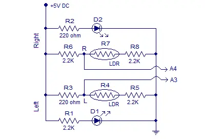
The sensor consists of two LED/LDR pairs with appropriate current limiting resistors. The resistance of an LDR is inversely proportional to the intensity of the light falling on it.  The circuit diagram of the sensor is shown in the figure below.
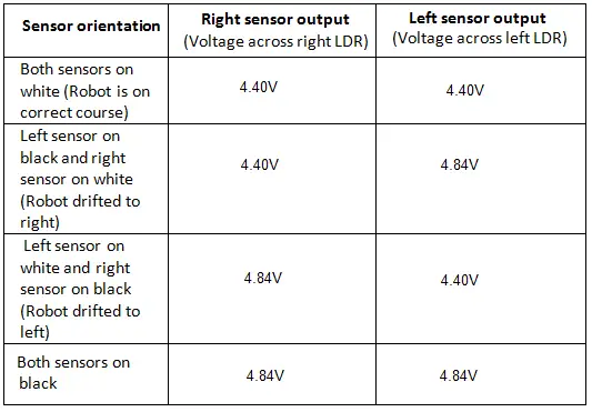
arduino line followerResistors R1 and R2 limits the current through the LEDs. Resistors R6, R8, R3,and R5 forms individual voltage divider networks in conjunction with the corresponding LDRs. When the sensor is correctly aligned, both LED/LDR pairs will over the white surface. In this condition sufficient amount of light gets reflected back to the LDRs and so their resistance will be low. So the voltage dropped across the LDR will be low. When the robot is drifted to  one side , the sensor in the opposite side falls over the black line and the intensity of light reflected back to the corresponding LDR  will be low. As a result the resistance of the LDR shoots up and the voltage dropped across it will be high. The voltages dropped across the right and left LDRs (nodes marked R and L in the above circuit)  are given as input to the analog input pins A4 and A3 of the Arduino board. Right and left sensor outputs observed while testing the above circuit is shown in the table below.
line follower robot using arduino

Arduino uno board.

The arduino board has to be programmed to keep the robot in correct path. This is done by reading the left and right sensor outputs and switching the left and right motors appropriately. Output of the right sensor is connected to the analog input A4 of the arduino and output of the left sensor is connected to the analog input A3 of the arduino. The voltage range that can be applied to a particular analog input of the arduino is 0 to 5V. This range can be converted into a digital value between 0 and 1023 using  analogRead () command.  For example if 3V is applied to A3,  the following code will return 3/(5/1023) which is equal to 613 in the variable leftValue.
int leftInput = A3;
int leftValue=0;
void loop ()
{
leftValue = analogRead (leftInput);
{
From the above table you can see that the voltage across a particular LDR will be 4.4V when it on white and 4.84V when it is on black. The digital equivalent of 4.4V will be 900 and that of 4.84V will be 990 as per the above scheme.  The median of these two values is 945 and it is set as the reference point for the program to check the orientation of the sensor module.
The program identifies the position of the sensor module by comparing the sensor readings with the reference point that is 945. If the reading of a particular sensor is greater than 945 the program can assume that the particular sensor is above black. If the reading of a particular sensor is less than 945 then it is assumed that the particular sensor is above white. If both sensor readings are less than 945 then it means both sensors are on white. If both sensor readings are above 945 it is assumed that both sensors are above black (the same thing happens if we lift the robot off the track). Based on the above four conditions, the program appropriately switches the left and right motors to keep the robot following the black line.

Motor driver.

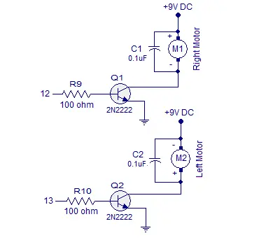
The motor driver circuit is based on two NPN transistors Q1 and Q2. Each transistors are wired as a switch with a resistor at its base for limiting the base current. The motors are connected to the emitter terminal of the corresponding transistors. A 0.1uF capacitor is connected across each motor  for by-passing the voltage spikes. Back emf  and arcing of brushes are the main reason behind the voltage spikes. If these voltage spikes are not by-passed it may affect the Arduino side.   Circuit diagram of the motor driver is shown in the figure below.
arduino line follower motor driver

Circuit diagram.

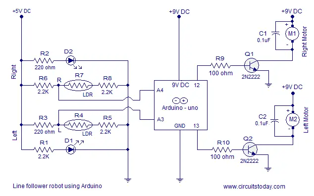
Full circuit diagram of the line follower robot  is shown in the figure below.
arduino line follower

Program.

int leftInput=A3;
int rightInput=A4;
int leftMotor=13;
int rightMotor=12;
int leftValue = 0;
int rightValue = 0;
void setup()
{
  pinMode (leftMotor, OUTPUT);
  pinMode (rightMotor, OUTPUT);
}
void loop()
{
  leftValue = analogRead (leftInput);
  rightValue= analogRead (rightInput);

 if
   ( leftValue < 945 && rightValue < 945)
   {
     digitalWrite (leftMotor, HIGH);
     digitalWrite (rightMotor, HIGH);
   }
   else
   {

     if
     ( leftValue > 945 && rightValue < 945)
    {
      digitalWrite (leftMotor, LOW);
      digitalWrite (rightMotor, HIGH);
    }
 else {
   if (leftValue < 945 && rightValue > 945)
   {
   digitalWrite (rightMotor, LOW);
   digitalWrite (leftMotor, HIGH);
   }
   else
   {
     if (leftValue > 945 && rightValue > 945)
     {digitalWrite (rightMotor, LOW);
       digitalWrite (leftMotor, LOW);
     }}
      }
    }}

Setting up the circuit.

  • First of all remember that each LED and LDR has its own characteristics.
  • Carefully measure the voltage across each LDRs in both scenarios (on white surface and black).
  • A lot of parameters like individual LDR/LED characteristics, ambient light, clearance between sensor and surface etc may affect the result.
  • Get in to your own reference point for the program. In my case it was 945 but you may get a different value.
  • Use a separate power supply unit for powering the motors. Anything above 100mA will be hard for the USB port.
  • The motors used here are 6V/30RPM DC bow motors. If such a configuration is not available, choose the closest one.
  • While soldering up the sensor module, the gap between the two LED/LDR pairs must be selected according to the width of the black line. In my case it was 2cm.
  • Clearance of the sensor from the ground was around 1cm in my case.
  • The sensor LEDs used were 4mm bright green LEDs.
  • The sensor LDRs used were general purpose LDRs.

[REPORT] Smart phone Android Operated Robot ,WIRELESS,BLUETOOTH


Some Importantant links below with reports.just view the link below. if u want any project report just search any project on our search box
Arduino interesting projects:   
Arduino 30 simple and good projects 
Atmega projects lists
Android Electronics projects lists
Rf based Projects with report
engineering study notes 
GSM GPS based projects with report
Bluetooth based projects with reports


Smart phone Android Operated Robot

The project aims in designing a Robot that can be operated using Android mobile
phone. The controlling of the Robot is done wirelessly through Android smart phone
using the Bluetooth feature present in it. Here in the project the Android smart phone is
used as a remote control for operating the Robot.
Android is a software stack for mobile devices that includes an operating system,
middleware and key applications. Android boasts a healthy array of connectivity options,
including Wi-Fi, Bluetooth, and wireless data over a cellular connection (for example,
GPRS, EDGE (Enhanced Data rates for GSM Evolution), and 3G). Android provides
access to a wide range of useful libraries and tools that can be used to build rich
applications. In addition, Android includes a full set of tools that have been built from the
ground up alongside the platform providing developers with high productivity and deep
insight into their applications.
Bluetooth is an open standard specification for a radio frequency (RF)-based,
short-range connectivity technology that promises to change the face of computing and
wireless communication. It is designed to be an inexpensive, wireless networking system
for all classes of portable devices, such as laptops, PDAs (personal digital assistants), and
mobile phones. It also will enable wireless connections for desktop computers, making
connections between monitors, printers, keyboards, and the CPU cable-free.
The controlling device of the whole system is a Microcontroller. Bluetooth
module, DC motors are interfaced to the Microcontroller. The data received by the
Bluetooth module from Android smart phone is fed as input to the controller. The
controller acts accordingly on the DC motors of the Robot. The robot in the project can
be made to move in all the four directions using the Android phone. The direction of the
robot is indicated using LED indicators of the Robot system. In achieving the task the
controller is loaded with a program written using Embedded ‘C’ language.

Proposal Smart phone Android Operated Robot

Some Importantant links below with reports.just view the link below. if u want any project report just search any project on our search box
Arduino interesting projects:   
Arduino 30 simple and good projects 
Atmega projects lists
Android Electronics projects lists
Rf based Projects with report
engineering study notes 
GSM GPS based projects with report
Bluetooth based projects with reports


Smart phone Android Operated Robot

The project aims in designing a Robot that can be operated using Android mobile
phone. The controlling of the Robot is done wirelessly through Android smart phone
using the Bluetooth feature present in it. Here in the project the Android smart phone is
used as a remote control for operating the Robot.
Android is a software stack for mobile devices that includes an operating system,
middleware and key applications. Android boasts a healthy array of connectivity options,
including Wi-Fi, Bluetooth, and wireless data over a cellular connection (for example,
GPRS, EDGE (Enhanced Data rates for GSM Evolution), and 3G). Android provides
access to a wide range of useful libraries and tools that can be used to build rich
applications. In addition, Android includes a full set of tools that have been built from the
ground up alongside the platform providing developers with high productivity and deep
insight into their applications.
Bluetooth is an open standard specification for a radio frequency (RF)-based,
short-range connectivity technology that promises to change the face of computing and
wireless communication. It is designed to be an inexpensive, wireless networking system
for all classes of portable devices, such as laptops, PDAs (personal digital assistants), and
mobile phones. It also will enable wireless connections for desktop computers, making
connections between monitors, printers, keyboards, and the CPU cable-free.
The controlling device of the whole system is a Microcontroller. Bluetooth
module, DC motors are interfaced to the Microcontroller. The data received by the
Bluetooth module from Android smart phone is fed as input to the controller. The
controller acts accordingly on the DC motors of the Robot. The robot in the project can
be made to move in all the four directions using the Android phone. The direction of the
robot is indicated using LED indicators of the Robot system. In achieving the task the
controller is loaded with a program written using Embedded ‘C’ language.

proposal Arduino Robot

Arduino Robot

Robot Top Robot Bottom

Overview

The Arduino Robot is the first official Arduino on wheels. The robot has two processors, one on each of its two boards. The Motor Board controls the motors, and the Control Board reads sensors and decides how to operate. Each of the boards is a full Arduino board programmable using the Arduino IDE.
Both Motor and Control boards are microcontroller boards based on the ATmega32u4 (datasheet). The Robot has many of its pins mapped to on-board sensors and actuators.
Programming the robot is similar to the process with the Arduino Leonardo. Both processors have built-in USB communication, eliminating the need for a secondary processor. This allows the Robot to appear to a connected computer as a virtual (CDC) serial / COM port.
As always with Arduino, every element of the platform – hardware, software and documentation – is freely available and open-source. This means you can learn exactly how it's made and use its design as the starting point for your own robots. The Arduino Robot is the result of the collective effort from an international team looking at how science can be made fun to learn. Arduino is now on wheels, come ride with us!

Control Board Summary

MicrocontrollerATmega32u4
Operating Voltage5V
Input Voltage5V through flat cable
Digital I/O Pins5
PWM Channels6
Analog Input Channels4 (of the Digital I/O pins)
Analog Input Channels (multiplexed)8
DC Current per I/O Pin40 mA
Flash Memory32 KB (ATmega32u4) of which 4 KB used by bootloader
SRAM2.5 KB (ATmega32u4)
EEPROM (internal)1 KB (ATmega32u4)
EEPROM (external)512 Kbit (I2C)
Clock Speed16 MHz
Keypad5 keys
Knobpotentiomenter attached to analog pin
Full color LCDover SPI communication
SD card readerfor FAT16 formatted cards
Speaker8 Ohm
Digital Compassprovides deviation from the geographical north in degrees
I2C soldering ports3
Prototyping areas4

Motor Board Summary

MicrocontrollerATmega32u4
Operating Voltage5V
Input Voltage9V to battery charger
AA battery slot4 alkaline or NiMh rechargeable batteries
Digital I/O Pins4
PWM Channels1
Analog Input Channles4 (same as the Digital I/O pins)
DC Current per I/O Pin40 mA
DC-DC convertergenerates 5V to power up the whole robot
Flash Memory32 KB (ATmega32u4) of which 4 KB used by bootloader
SRAM2.5 KB (ATmega32u4)
EEPROM1 KB (ATmega32u4)
Clock Speed16 MHz
Trimmerfor movement calibration
IR line following sensors5
I2C soldering ports1
Prototyping areas2

Schematic & Reference Design

EAGLE files for control and motor boards: arduino-robot-reference-design.zip

Power

The Arduino Robot can be powered via the USB connection or with 4 AA batteries. The power source is selected automatically.
The battery holder holds 4 rechargeable NiMh AA batteries.
NB : Do not use non-rechargeable batteries with the robot
For safety purposes, the motors are disabled when the robot is powered from the USB connection.
The robot has an on-board battery charger that requires 9V external power coming from an AC-to-DC adapter (wall-wart). The adapter can be connected by plugging a 2.1mm center-positive plug into the Motor Board's power jack. The charger will not operate if powered by USB.
The Control Board is powered by the power supply on the Motor Board.

Memory

The ATmega32u4 has 32 KB (with 4 KB used for the bootloader). It also has 2.5 KB of SRAM and 1 KB of EEPROM (which can be read and written with the EEPROM library).
The Control Board has an extra 512 Kbit EEPROM that can be accessed via I2C.
There is an external SD card reader attached to the GTFT screen that can be accessed by the Control Board's processor for additional storage.

Input and Output

The Robot comes with a series of pre-soldered connectors. There are a number of additional spots for you to install additional parts if needed.
All the connectors are labelled on the boards and mapped to named ports through the Robot library allowing access to standard Arduino functions. Each pin can provide or receive a maximum of 40mA at 5V.
Some pins have specialized functions :
  • Control Board TK0 to TK7: these pins are multiplexed to a single analog pin on theControl Board's microprocessor. They can be used as analog inputs for sensors like distance sensors, analog ultrasound sensors, or mechanical switches to detect collisions.
  • Control Board TKD0 to TKD5: these are digital I/O pins directly connected to the processor, addressed using Robot.digitalRead() and Robot.digitalWrite) functions. Pins TKD0 to TKD3 can also be used as analog inputs with Robot.analogRead()
    Note: if you have one of the first generation robots, you will see that the TKD* pins are named TDK* on the Robot's silkscreen. TKD* is the proper name for them and is how we address them on the software.
  • Serial Communication: The boards communicate with each other using the processors' serial port. A 10-pin connector connects both boards carries the serial communication, as well as power and additional information like the battery's current charge.
  • Control Board SPI: SPI is used to control the GTFT and SD card. If you want to flash the processor using an external programmer, you need to disconnect the screen first.
  • Control Board LEDs: the Control Board has three on-board LEDs. One indicates the board is powered (PWR). The other two indicate communication over the USB port (LED1/RX and TX). LED1 is also accessible via software.
  • Both boards have I2C connectors available: 3 on the Control Board and 1 on the Motor Board.

Control Board Pin Mapping

ARDUINO LEONARDOARDUINO ROBOT CONTROLATMEGA 32U4FUNCTIONREGISTER
D0RXPD2RXRXD1/INT2
D1TXPD3TXTXD1/INT3
D2SDAPD1SDASDA/INT1
D3#SCLPD0PWM8/SCLOC0B/SCL/INT0
D4MUX_IN A6PD4
ADC8
D5#BUZZPC6???OC3A/#OC4A
D6#MUXA/TKD4 A7PD7FastPWM#OC4D/ADC10
D7RST_LCDPE6
INT6/AIN0
D8CARD_CS A8PB4
ADC11/PCINT4
D9#LCD_CS A9PB5PWM16OC1A/#OC4B/ADC12/PCINT5
D10#DC_LCD A10PB6PWM16OC1B/0c4B/ADC13/PCINT6
D11#MUXBPB7PWM8/160C0A/OC1C/#RTS/PCINT7
D12MUXC/TKD5 A11PD6
T1/#OC4D/ADC9
D13#MUXDPC7PWM10CLK0/OC4A
A0KEY D18PF7
ADC7
A1TKD0 D19PF6
ADC6
A2TKD1 D20PF5
ADC5
A3TKD2 D21PF4
ADC4
A4TKD3 D22PF1
ADC1
A5POT D23PF0
ADC0
MISOMISO D14PB3
MISO,PCINT3
SCKSCK D15PB1
SCK,PCINT1
MOSIMOSI D16PB2
MOSI,PCINT2
SSRX_LED D17PB0
RXLED,SS/PCINT0
TXLEDTX_LEDPD5

HWB
PE2
HWB

Motor Board Pin Mapping

ARDUINO LEONARDOARDUINO ROBOT CONTROLATMEGA 32U4FUNCTIONREGISTER
D0RXPD2RXRXD1/INT2
D1TXPD3TXTXD1/INT3
D2SDAPD1SDASDA/INT1
D3#SCLPD0PWM8/SCLOC0B/SCL/INT0
D4TK3 A6PD4
ADC8
D5#INA2PC6???OC3A/#OC4A
D6#INA1 A7PD7FastPWM#OC4D/ADC10
D7MUXAPE6
INT6/AIN0
D8MUXB A8PB4
ADC11/PCINT4
D9#INB2 A9PB5PWM16OC1A/#OC4B/ADC12/PCINT5
D10#INB1 A10PB6PWM16OC1B/0c4B/ADC13/PCINT6
D11#MUXCPB7PWM8/160C0A/OC1C/#RTS/PCINT7
D12TK4 A11PD6
T1/#OC4D/ADC9
D13#MUXIPC7PWM10CLK0/OC4A
A0TK1 D18PF7
ADC7
A1TK2 D19PF6
ADC6
A2MUX_IN D20PF5
ADC5
A3TRIM D21PF4
ADC4
A4SENSE_A D22PF1
ADC1
A5SENSE_B D23PF0
ADC0
MISOMISO D14PB3
MISO,PCINT3
SCKSCK D15PB1
SCK,PCINT1
MOSIMOSI D16PB2
MOSI,PCINT2
SSRX_LED D17PB0
RXLED,SS/PCINT0
TXLEDTX_LEDPD5

HWB
PE2
HWB

Communication

The Robot has a number of facilities for communicating with a computer, another Arduino, or other microcontrollers. The ATmega32U4 provides UART TTL (5V) serial communication, which is available on digital the 10-pin board-to-board connector. The 32U4 also allows for serial (CDC) communication over USB and appears as a virtual com port to software on the computer. The chip also acts as a full speed USB 2.0 device, using standard USB COM drivers. On Windows, a .inf file is required. The Arduino software includes a serial monitor which allows simple textual data to be sent to and from the Robot board. The RX (LED1) and TX LEDs on the board will flash when data is being transmitted via the USB connection to the computer (but not for serial communication between boards).
Each one of the boards has a separate USB product identifier and will show up as different ports on you IDE. Make sure you choose the right one when programming.
The ATmega32U4 also supports I2C (TWI) and SPI communication. The Arduino software includes a Wire library to simplify use of the I2C bus; see the documentation for details. For SPI communication, use the SPI library.

Programming

The Robot can be programmed with the Arduino software (download). Select "Arduino Robot Control Board" or "Arduino Robot Motor Board" from the Tools > Board menu. For details, see the getting started page and tutorials.
The ATmega32U4 processors on the Arduino Robot come preburned with a bootloader that allows you to upload new code to it without the use of an external hardware programmer. It communicates using the AVR109 protocol.
You can bypass the bootloader and program the microcontroller through the ICSP (In-Circuit Serial Programming) header; see these instructions for details.

Automatic (Software) Reset and Bootloader Initiation

Rather than requiring a physical press of the reset button before an upload, the Robot is designed in a way that allows it to be reset by software running on a connected computer. The reset is triggered when the Robot's virtual (CDC) serial / COM port is opened at 1200 baud and then closed. When this happens, the processor will reset, breaking the USB connection to the computer (meaning that the virtual serial / COM port will disappear). After the processor resets, the bootloader starts, remaining active for about 8 seconds. The bootloader can also be initiated by double-pressing the reset button on the Robot. Note that when the board first powers up, it will jump straight to the user sketch, if present, rather than initiating the bootloader.
Because of the way the Robot handles reset it's best to let the Arduino software try to initiate the reset before uploading, especially if you are in the habit of pressing the reset button before uploading on other boards. If the software can't reset the board you can always start the bootloader by double-pressing the reset button on the board. A single press on the reset will restart the user sketch, a double press will initiate the bootloader.

USB Overcurrent Protection

Both of the Robot boards have a resettable polyfuse that protects your computer's USB ports from shorts and overcurrent. Although most computers provide their own internal protection, the fuse provides an extra layer of protection. If more than 500 mA is applied to the USB port, the fuse will automatically break the connection until the short or overload is removed.

Physical Characteristics

The Robot is 19cm in diameter. Including wheels, GTFT screen and other connectors it can be up to 10cm tall.
Some Importantant links below with reports.just view the lik below
Arduino interesting projects:   
Arduino 30 simple and good projects 
Atmega projects lists
Android Electronics projects lists
Rf based Projects with report
engineering study notes 
GSM GPS based projects with report
Bluetooth based projects with reports


if u like the post just say thank u in comment box.

[ REPORT ] The Robot control using the wireless communication and the serial communication

 Abstract:

 This project outlines the strategy adopted for establishing two kinds of communications; one for wireless communication between a mobile Robot and a remote Base Station, another for serial communication between a remote Base Station and a GUI Application, PC. TekBot is a low cost mobile Robot built by Oregon State University which in its current version requires wired communication. Our aim is to be able to command and control the Robot wirelessly by the GUI Application. This will be a useful addition for NASA’s curriculum development for master’s degree programs.
  The principle task of this project was to program the AVR microcontroller interfaced to a radio packet controller module (operating at a frequency of 433 MHz) which would enable us to wirelessly control the Robot. The communication protocols dealing with transmission and reception of data and wireless control of the TekBot have been successfully implemented. These details are discussed in this report.

1. Introduction

The NASA Robotics Alliance Cadets Program is a far-reaching, innovative project aimed at creating a new highly integrated and interactive college undergraduate level curriculum centered around Robotics and focusing on the content of at least the first two years of Mechanical Engineering, Electrical Engineering and Computer Science. This project is being co-led by Mark Leon, NASA AMES Director of Education and David Schneider of Cornell University and is supported by David Lavery, NASA Program Executive of Planetary and Solar Exploration. The program is being designed to be implemented at a very low start-up cost, and to make this goal obtainable, the program is being developed using low to no cost components from already developed, well-tested and robust engineering testbeds. The Microcontroller board to be used is the Oregon State University TekBots platforms, whose base kit is approximately $100.

DOWNLOAD THIS FULL PROJECT REPORT HERE
if u like the post just say thank u in comment box.

Voice operated Intelligent Fire extinguisher vehicle

The project aims at designing an intelligent voice operated fire extinguishingrobotic vehicle which can be controlled wirelessly through RF communication. TheRobotic vehicle has a camera mounted on it whose direction can also be controlled usingvoice commands. 
The proposed vehicle has a water jet spray which is capable ofsprinkling water. The sprinkler can be moved towards the required direction.
The advent of new high-speed technology provided realistic opportunity for new
robot controls and realization of new methods of control theory. This technical
improvement together with the need for high performance robots created faster, more
accurate and more intelligent robots using new robots control devices, new drivers and
advanced control algorithms. This project describes a new economical solution of robot
control systems. The presented robot control system can be used for different
sophisticated robotic applications.
Speech is the primary and most convenient means of communication between
humans. Whether due to technological curiosity to build machines that mimic human’s or
desire to automate work with machine, research in speech recognition as a first step
towards human-machine communication. Speech recognition is the process of
recognizing the spoken word to take necessary actions accordingly.
The controlling devices of the whole system are Microcontrollers. Speech
recognition module, wireless transceiver modules, obstacle detector, lamp, water jetspray, DC motors and buzzer are interfaced to Microcontroller. When the user fed the
voice commands to the speech recognition module, the microcontroller interfaced to it
reads the command and sends relevant data of that command wirelessly using transceiver
module. This data is received by the transceiver module on the robotic vehicle and feds it
to microcontroller which acts accordingly on motors, pump and lamp. The vehicle is
mounted with a camera which helps in viewing the live images on TV. Also, the vehicle
is capable of detecting obstacles and alerts the user through buzzer. To perform this

SEE THE PREWIEW AND DOWNLOAD HERE
if u like the post just say thank u in comment box.

[ Report ] ROBOT ARDUINO

Some Importantant links below with reports.just view the lik below
Arduino interesting projects:   
Arduino 30 simple and good projects 
Atmega projects lists
Android Electronics projects lists
Rf based Projects with report
engineering study notes 
GSM GPS based projects with report
Bluetooth based projects with reports

For other  interesting ARDUINO PROJECTS here

Arduino Robot

Robot Top Robot Bottom

Overview

The Arduino Robot is the first official Arduino on wheels. The robot has two processors, one on each of its two boards. The Motor Board controls the motors, and the Control Board reads sensors and decides how to operate. Each of the boards is a full Arduino board programmable using the Arduino IDE.
Both Motor and Control boards are microcontroller boards based on the ATmega32u4 (datasheet). The Robot has many of its pins mapped to on-board sensors and actuators.
Programming the robot is similar to the process with the Arduino Leonardo. Both processors have built-in USB communication, eliminating the need for a secondary processor. This allows the Robot to appear to a connected computer as a virtual (CDC) serial / COM port.
As always with Arduino, every element of the platform – hardware, software and documentation – is freely available and open-source. This means you can learn exactly how it's made and use its design as the starting point for your own robots. The Arduino Robot is the result of the collective effort from an international team looking at how science can be made fun to learn. Arduino is now on wheels, come ride with us!

Control Board Summary

MicrocontrollerATmega32u4
Operating Voltage5V
Input Voltage5V through flat cable
Digital I/O Pins5
PWM Channels6
Analog Input Channels4 (of the Digital I/O pins)
Analog Input Channels (multiplexed)8
DC Current per I/O Pin40 mA
Flash Memory32 KB (ATmega32u4) of which 4 KB used by bootloader
SRAM2.5 KB (ATmega32u4)
EEPROM (internal)1 KB (ATmega32u4)
EEPROM (external)512 Kbit (I2C)
Clock Speed16 MHz
Keypad5 keys
Knobpotentiomenter attached to analog pin
Full color LCDover SPI communication
SD card readerfor FAT16 formatted cards
Speaker8 Ohm
Digital Compassprovides deviation from the geographical north in degrees
I2C soldering ports3
Prototyping areas4

Motor Board Summary

MicrocontrollerATmega32u4
Operating Voltage5V
Input Voltage9V to battery charger
AA battery slot4 alkaline or NiMh rechargeable batteries
Digital I/O Pins4
PWM Channels1
Analog Input Channles4 (same as the Digital I/O pins)
DC Current per I/O Pin40 mA
DC-DC convertergenerates 5V to power up the whole robot
Flash Memory32 KB (ATmega32u4) of which 4 KB used by bootloader
SRAM2.5 KB (ATmega32u4)
EEPROM1 KB (ATmega32u4)
Clock Speed16 MHz
Trimmerfor movement calibration
IR line following sensors5
I2C soldering ports1
Prototyping areas2

Schematic & Reference Design

EAGLE files for control and motor boards: arduino-robot-reference-design.zip

Power

The Arduino Robot can be powered via the USB connection or with 4 AA batteries. The power source is selected automatically.
The battery holder holds 4 rechargeable NiMh AA batteries.
NB : Do not use non-rechargeable batteries with the robot
For safety purposes, the motors are disabled when the robot is powered from the USB connection.
The robot has an on-board battery charger that requires 9V external power coming from an AC-to-DC adapter (wall-wart). The adapter can be connected by plugging a 2.1mm center-positive plug into the Motor Board's power jack. The charger will not operate if powered by USB.
The Control Board is powered by the power supply on the Motor Board.

Memory

The ATmega32u4 has 32 KB (with 4 KB used for the bootloader). It also has 2.5 KB of SRAM and 1 KB of EEPROM (which can be read and written with the EEPROM library).
The Control Board has an extra 512 Kbit EEPROM that can be accessed via I2C.
There is an external SD card reader attached to the GTFT screen that can be accessed by the Control Board's processor for additional storage.

Input and Output

The Robot comes with a series of pre-soldered connectors. There are a number of additional spots for you to install additional parts if needed.
All the connectors are labelled on the boards and mapped to named ports through the Robot library allowing access to standard Arduino functions. Each pin can provide or receive a maximum of 40mA at 5V.
Some pins have specialized functions :
  • Control Board TK0 to TK7: these pins are multiplexed to a single analog pin on theControl Board's microprocessor. They can be used as analog inputs for sensors like distance sensors, analog ultrasound sensors, or mechanical switches to detect collisions.
  • Control Board TKD0 to TKD5: these are digital I/O pins directly connected to the processor, addressed using Robot.digitalRead() and Robot.digitalWrite) functions. Pins TKD0 to TKD3 can also be used as analog inputs with Robot.analogRead()
    Note: if you have one of the first generation robots, you will see that the TKD* pins are named TDK* on the Robot's silkscreen. TKD* is the proper name for them and is how we address them on the software.
  • Serial Communication: The boards communicate with each other using the processors' serial port. A 10-pin connector connects both boards carries the serial communication, as well as power and additional information like the battery's current charge.
  • Control Board SPI: SPI is used to control the GTFT and SD card. If you want to flash the processor using an external programmer, you need to disconnect the screen first.
  • Control Board LEDs: the Control Board has three on-board LEDs. One indicates the board is powered (PWR). The other two indicate communication over the USB port (LED1/RX and TX). LED1 is also accessible via software.
  • Both boards have I2C connectors available: 3 on the Control Board and 1 on the Motor Board.

Control Board Pin Mapping

ARDUINO LEONARDOARDUINO ROBOT CONTROLATMEGA 32U4FUNCTIONREGISTER
D0RXPD2RXRXD1/INT2
D1TXPD3TXTXD1/INT3
D2SDAPD1SDASDA/INT1
D3#SCLPD0PWM8/SCLOC0B/SCL/INT0
D4MUX_IN A6PD4ADC8
D5#BUZZPC6???OC3A/#OC4A
D6#MUXA/TKD4 A7PD7FastPWM#OC4D/ADC10
D7RST_LCDPE6INT6/AIN0
D8CARD_CS A8PB4ADC11/PCINT4
D9#LCD_CS A9PB5PWM16OC1A/#OC4B/ADC12/PCINT5
D10#DC_LCD A10PB6PWM16OC1B/0c4B/ADC13/PCINT6
D11#MUXBPB7PWM8/160C0A/OC1C/#RTS/PCINT7
D12MUXC/TKD5 A11PD6T1/#OC4D/ADC9
D13#MUXDPC7PWM10CLK0/OC4A
A0KEY D18PF7ADC7
A1TKD0 D19PF6ADC6
A2TKD1 D20PF5ADC5
A3TKD2 D21PF4ADC4
A4TKD3 D22PF1ADC1
A5POT D23PF0ADC0
MISOMISO D14PB3MISO,PCINT3
SCKSCK D15PB1SCK,PCINT1
MOSIMOSI D16PB2MOSI,PCINT2
SSRX_LED D17PB0RXLED,SS/PCINT0
TXLEDTX_LEDPD5
HWBPE2HWB

Motor Board Pin Mapping

ARDUINO LEONARDOARDUINO ROBOT CONTROLATMEGA 32U4FUNCTIONREGISTER
D0RXPD2RXRXD1/INT2
D1TXPD3TXTXD1/INT3
D2SDAPD1SDASDA/INT1
D3#SCLPD0PWM8/SCLOC0B/SCL/INT0
D4TK3 A6PD4ADC8
D5#INA2PC6???OC3A/#OC4A
D6#INA1 A7PD7FastPWM#OC4D/ADC10
D7MUXAPE6INT6/AIN0
D8MUXB A8PB4ADC11/PCINT4
D9#INB2 A9PB5PWM16OC1A/#OC4B/ADC12/PCINT5
D10#INB1 A10PB6PWM16OC1B/0c4B/ADC13/PCINT6
D11#MUXCPB7PWM8/160C0A/OC1C/#RTS/PCINT7
D12TK4 A11PD6T1/#OC4D/ADC9
D13#MUXIPC7PWM10CLK0/OC4A
A0TK1 D18PF7ADC7
A1TK2 D19PF6ADC6
A2MUX_IN D20PF5ADC5
A3TRIM D21PF4ADC4
A4SENSE_A D22PF1ADC1
A5SENSE_B D23PF0ADC0
MISOMISO D14PB3MISO,PCINT3
SCKSCK D15PB1SCK,PCINT1
MOSIMOSI D16PB2MOSI,PCINT2
SSRX_LED D17PB0RXLED,SS/PCINT0
TXLEDTX_LEDPD5
HWBPE2HWB

Communication

The Robot has a number of facilities for communicating with a computer, another Arduino, or other microcontrollers. The ATmega32U4 provides UART TTL (5V) serial communication, which is available on digital the 10-pin board-to-board connector. The 32U4 also allows for serial (CDC) communication over USB and appears as a virtual com port to software on the computer. The chip also acts as a full speed USB 2.0 device, using standard USB COM drivers. On Windows, a .inf file is required. The Arduino software includes a serial monitor which allows simple textual data to be sent to and from the Robot board. The RX (LED1) and TX LEDs on the board will flash when data is being transmitted via the USB connection to the computer (but not for serial communication between boards).
Each one of the boards has a separate USB product identifier and will show up as different ports on you IDE. Make sure you choose the right one when programming.
The ATmega32U4 also supports I2C (TWI) and SPI communication. The Arduino software includes a Wire library to simplify use of the I2C bus; see the documentation for details. For SPI communication, use the SPI library.

Programming

The Robot can be programmed with the Arduino software (download). Select "Arduino Robot Control Board" or "Arduino Robot Motor Board" from the Tools > Board menu. For details, see the getting started page and tutorials.
The ATmega32U4 processors on the Arduino Robot come preburned with a bootloader that allows you to upload new code to it without the use of an external hardware programmer. It communicates using the AVR109 protocol.
You can bypass the bootloader and program the microcontroller through the ICSP (In-Circuit Serial Programming) header; see these instructions for details.

Automatic (Software) Reset and Bootloader Initiation

Rather than requiring a physical press of the reset button before an upload, the Robot is designed in a way that allows it to be reset by software running on a connected computer. The reset is triggered when the Robot's virtual (CDC) serial / COM port is opened at 1200 baud and then closed. When this happens, the processor will reset, breaking the USB connection to the computer (meaning that the virtual serial / COM port will disappear). After the processor resets, the bootloader starts, remaining active for about 8 seconds. The bootloader can also be initiated by double-pressing the reset button on the Robot. Note that when the board first powers up, it will jump straight to the user sketch, if present, rather than initiating the bootloader.
Because of the way the Robot handles reset it's best to let the Arduino software try to initiate the reset before uploading, especially if you are in the habit of pressing the reset button before uploading on other boards. If the software can't reset the board you can always start the bootloader by double-pressing the reset button on the board. A single press on the reset will restart the user sketch, a double press will initiate the bootloader.

USB Overcurrent Protection

Both of the Robot boards have a resettable polyfuse that protects your computer's USB ports from shorts and overcurrent. Although most computers provide their own internal protection, the fuse provides an extra layer of protection. If more than 500 mA is applied to the USB port, the fuse will automatically break the connection until the short or overload is removed.

Physical Characteristics

The Robot is 19cm in diameter. Including wheels, GTFT screen and other connectors it can be up to 10cm tall.
Some Importantant links below with reports.just view the lik below
Arduino interesting projects:   
Arduino 30 simple and good projects 
Atmega projects lists
Android Electronics projects lists
Rf based Projects with report
engineering study notes 
GSM GPS based projects with report
Bluetooth based projects with reports


if u like the post just say thank u in comment box.

[ REPORT ] WIFI CONTROLLED ROBOT

THE FOLLOWING LINK ENABLES YOU TO TH E DOWNLOAD SECTON OF 

[ REPORT ] WIFI SMART ROBOT

[REPORT ] WIFI ENABLED ROBOT

For other  interesting ARDUINO PROJECTS here

 JUST INTRODUCING

WIFIenabled Robot is a system, which
controls the turtle robot using the web page. To make
this feasible we make use of the HNZG1 board with a
built in Micro controller and ZeroG-2100 Wi-Fi
module. HNZG1 board is developed exclusively by
MANIPAL DOT NET PVT. LTD comprises of ZeroG-
2100 module for wireless connectivity and inbuilt
PIC24F series microcontroller from Microchip
Technology Inc.
Switch control mode of Robot is controlled
using Joystick and can appropriately be guided to back,
forth, left and right directions
So in this project, we extend an interface to
the Switch control mode to suit our requirements.
Finally we have been able to bridge together the
HNZG1 board and the Turtle Robot, and eventually
control the Turtle Robot in wireless environment
through the control buttons embedded on the custom
Web page designed by us.

if u like the post just say thank u in comment box.

[ REPORT ] Obstacle detection Robot with Ultrasonic Sensors


Obstacle Avoidance with Ultrasonic Sensors

JOHANN BORENSTEIN AND YORAM KOREN

Abstract-

A mobile robot system, capable of performing various tasks
for the physically disabled, has been developed. To avoid collision with
unexpected obstacles, the mobile robot uses ultrasonic range finders for
detection and mapping. The obstacle avoidance strategy used for this
robot is described. Since this strategy depends heavily on the performance
of the ultrasonic range finders, these sensors and the effect of their
limitations on the obstacle avoidance algorithm are discussed in detail.

I. INTRODUCTION

This communication describes some features of a mobile nursing
robot system, which is produced as an aid for bedridden who acquire
constant assistance for the most elementary needs. Such a device, it is
hoped, will return a measure of independence to many bedridden
persons as well as reducing the number of those in need of
hospitalization and constant attendance [22], [23]. The workspace of
the nursing robot would be usually confined to one room, either in a

[ SYSTEM DESCRIPTION] EIRELESS CONTROLLED ROBOTIC ARM

[REPORT]WIRELESS CONTROLLED ROBOTIC ARM

3.  SYSTEM DESCRIPTION

3.1            BLOCK DIAGRAM

The functional block diagram of our system is as follow:

FIGURE 3.1: BLOCK DIAGRAM OF THE SYSTEM


3.2            BLOCK DIAGRAM DESCRIPTION

            Overall block diagram is divided into two main parts. One is User side or Control panel and robot side. The robot is either controlled using joystick or via Control software at PC. The control signal is sent to robot from PC via the receiver microcontroller at Arduino board. The receiver microcontroller receives control signals from PC and forwards signal to the robot. The control signal refers to the mode selection signals, position signals for arm and base motors. Software sends signal serially via USB to microcontroller, microcontroller then forwards the signals via XBee RF module to next RF Module at robot side. Microcontroller to XBee communication is also serial communication.

            In Joystick mode, the position of joystick determines the position of arm. On the movement of joystick, TX microcontroller sends the angular position of joystick to the robot so that robot-side microcontroller could receive the angular position and command the servomotors to have desired position.


3.3         SYSTEM ALGORITHM

The system algorithm for our project is as below

Transmitter side

Step1: Start

Step2: XBee Initialization.

Step3: Check if it is in Arm Mode

            If yes: Goto step 4

            If No: Goto step 8

            Step4: Read analog value from POT.

Step 5: Convert analog integer into angular value.

Step 6: Create packet and send it via Radio Frequency Module

Step7: Goto Step 3 [Loop]

Step 8: Read which button s pressed

Step 9: Send control signal to control motion of dc motor according to button pressed

Step 10: Goto Step 3 [Loop]


Receiver Side

            Step 1: Start

            Step2:  Initialize XBee

            Step3: Read Serial Data and Analyze.

                        Check the Start Bytes of Packets [*@]

            Step 4: Found Start bits?

                        If Yes: Goto Step 5

Step 5:  Read six characters serially and assign each char corresponding to servo motor.

            Step 6: Goto Step 3

            Step 7: Read Start byte of packet [‘8’,’4’,’2’,’6’]

            Step 8: Correct sequence detected?

                        If yes: Goto Step 9

                        If No:  Goto Step 3

            Step 9: Control the corresponding movement of respective DC Motor.

            Step 10: Goto Step 3


            Note: char ‘8’ is followed by integer 8 to indicate that button UP is pressed.

            Two different bytes are used to indicate that DC motor control button is pressed.


3.4            SYSTEM OPERATION FLOWCHART


Transmitter side functional flow chart:


FIGURE 3.4 (a): FLOW DIAGRAM FOR TRANSMITTER


Oval: StartReceiver side functional flow chart:


FIGURE 3.4 (b): FLOW DIAGRAM FOR RECEIVER