Showing posts with label proposal. Show all posts

Project Proposal ONLINE AIR TICKETING SYSTEM


1.2 Introduction
Online air ticketing system is a system that uses Internet to issue the tickets of different airline. Using this system, any user can generate the tickets through the Internet basis. At the present state of the IT development people wants to get more facility by spending less time and less money. But the way of ticketing in Nepal is very tedious job. A person has to move from counter to counter to get their tickets. The online air ticketing system solves the problem of moving to various counters. It helps the user to generate the tickets by sitting in before a computer and browsing the Internet.
This system makes the travel easy and life very simple. Using this system the user can find various types of information like as time of flight, seat status, available seat, types of flight etc. The main function of this system is to help user to issue tickets of the airplane on the online basis. The user can generate the air tickets by sitting at home through the Internet. For this system the user should resister by using his or her email address, password, name etc. After the registration the user should login with that email address. The user is welcomed and the user is asked to type the date and to select the type of air ways. Then list of airline available is displayed in the monitor. The user selects the specific flight and place as destination place. After that the user has to enter the bank account number for the payment. If the payment is accepted the user gets the conformation letter. The user can get the air tickets by showing that paper in any office of the respective office of the air line.

Project Proposal “WIRELESS SENSOR NETWORK(WSN)”


PREFACE
Today is the time of technology and advancement. The world is in digital format where every pulse is counting for the next technology. Due to the boon of science we are able to forecast and pre-determine the next second in every fields. We can sense and measure the every parameter that is directly related in our life. For this sensors are introduced in our technology for efficient calculations and predictions. Sensors sense the external factors and represents in terms of measurable parameters of voltages and current. These are proved to be the most necessary factors not only in the field of electronics and but in every field of science and inventions. In previous times sensors were individually placed and used for sensing but due to advancing technology and needs the sensors are being used in many numbers in many places. All these sensors are interconnected through various ways forming a network .This sensor network are proved very useful for the field of research and study.
The ways of creating a network of sensors could be either wired or wireless. Whatever be the medium of communicating between the sensors or creating the network of the multiple sensors placed in various places, the main purpose is to receive sensor signal of various sensors placed at various places to analyze the various factors or study in broader scenario. Creating a sensor network is a tedious task where each sensor are to be synchronized and communicated within a network or even internetwork .A network of different sensors helps to analyze the conditions of different places. Sensors could be of any kind like seismic, rainfall, pressure, temperature, lightning or thunderstorm. Interconnection or interlink of sensors could be a powerful tool for forecast, analysis or study the pre conditions of any disaster or case study for research fields.
Here we intend to create a network of sensors in a wireless approach where each sensor will be RF modulated and the main host or receiver will access all the data of sensors in network in a synchronous way. The flexibility of inter sensor communications could be limited due to hardware interfacing but the main purpose of receiving the signal of various sensors places at different places is the main purpose of the project.

Project Proposal Meter Reading Through Pstn Line


ABSTRACT
In today’s modern era, means of communication is developing day by day with the added features. Further enhancement, compatible and economical must be the property of the project. Telephony is one of the most widely used means of fast and the reliable communication. Keeping this in mind we have put forward the data transmission project in the PSTN lines.
The project entitled “Meter Reading through PSTN Line” is an intelligent system which can be used to measure, record, and display the data of electricity consumption, from the central office. We use the interface card to measure the units of electricity consumed by every subscriber in his household. The pulse signal obtaining from the electric meter is counted for the purpose of recording the units. The recorded digital data stored in the interface card must be transmitted to the central office when it detects a valid call from the central office. A caller id system is required to detect the call whether it is originated from the central office or somewhere else. Our project is fully embedded system based and all the control actions are performed using the microcontrollers including caller id detection, relay switching, auto hook off, counting the meter pulses, and driving the DTMF circuits of the PSTN line. Simply it is the master device to perform all the necessary action. Further we can easily program the device in assembly as well as high level language like C. The data received in the central office is displayed on the LCD. And finally those digital data obtained in central office are used for displaying, storing and manipulated for the billing purpose.

Proposal &report Computer Controlled wireless wired Robot

Building a computer controlled wireless robot

  As we always concern on the  cheapest and easiest way to control electronic devices wirelessly using a computer.  For example, you could build a radio controlled relay board, and control it from your computer. You could even control the board with a "small" computer such as an Arduino . If your Arduino has an Ethernet shield, you could use it as a Web server and control your relay board from anywhere in the world (as long as you have access to the Internet of course). There are many things that you could do without creating a mess with wires. I am mainly interested in this because I need a computer controlled wireless robot. A little background -

I have been working on a project at the Mobile Robotics Lab of IISc (Indian Institute of Science), Bangalore, in which I have to design a vision based obstacle avoidance algorithm for robots. What does that mean? Well, I basically have to design a robot that uses nothing but a small camera to identify obstacles in its path. Since image processing and computer vision stuff is usually quite CPU intensive, it is difficult to implement this code on a small robot. Small microcontrollers can't handle that stuff. So, the solution I came up with involves a wireless camera that transmits video to a nearby "big" computer. This big computer runs all the dirty computer vision codes, identifies the obstacles, and then somehow tells the robot how to avoid them. This is where wireless communication comes in.

To create a wireless link, you could rip the guts of a cheap RC car and use its transmitter and receiver to control your robot. That's one technique. I did something similar a few years ago . This time, I wanted to do things a little more elegantly, without destroying an RC car. I found this really inexpensive RF transmitter/receiver pair at a local electronics shop in Bangalore:


They cost only 200 INR (about 4 USD)...both transmitter and receiver.Isnt its so cheap.

You can also find these online at Sparkfun:

Transmitter - http://www.sparkfun.com/products/8945
Receiver - http://www.sparkfun.com/products/8948


They cost a little more on Sparkfun, but they're still inexpensive. The ones on Sparkfun operate at 315 Mhz, but the ones I have, operate at 434 Mhz (like this one). I don't think that would make any difference in how you connect them.
To use these cheap RF modules, you could either connect them directly to your microcontroller/computer, or connect them with the help of parallel - serial encoder/decoder ICs.

I used the HT12E (parallel to serial encoder) and the HT12D (serial to parallel decoder) ICs. The HT12E is a 12 bit parallel to serial encoder. Of those 12 bits, 8 bits are the address code, and the remaining 4 bits are data. To send a signal, the address bits on the transmitter and receiver should be the same. It's like a password. You can use a single RF transmitter to control different RF receivers (at the same frequency) by configuring the address bits appropriately. All receivers would have to be set to different addresses. With 8 bits, you can create a total of 256 combinations.


Display of serial data coming out of the encoder looks like, in an oscilloscope:


If you look closely, you'll notice that there are 13 peaks (instead of 12). I'm not sure what the first bit is for. (Probably a parity bit?) The 8 bits coming after the first bit make the address, and the last four make the data being sent. You connect your microcontroller's (or computer's) parallel output to the 4 input channels on the encoder. With 4 bits, you can create 16 unique commands. That is enough for my purpose.

For more on how to use these ICs with the Tx/Rx, check out this excellent article - http://www.botskool.com/tutorials/electronics/general-electronics/building-rf-remote-control
I've connected an Arduino to my computer which acts as an interface between the encoder and my computer. Here's the Arduino that I'm using:


It's a ModernDevice BBB Arduino Clone that I received from my friend Tom Boyd. I've been hooked to it ever since I got it! You should definitely get an Arduino if you don't already have one. It's the perfect tool for the programmer who enjoys playing with electronics. And it's also very easy and fun to use!

Tom has some excellent tutorials on electronics and programming on his website that keeps inspiring me! Check out some of his awesome Arduino projects - http://sheepdogguide
cools.com/arduino/ahttoc.htm.

The robot I am using is a Microbric Viper robot that I received from Microbric a few years ago. The Microbric Viper comes with an IR module which can be used to communicate with a computer wirelessly. Although I've used it in the past, it's kind of difficult to set up because infrared communication requires line-of-sight. Moreover, the range is quite limited.


I'm not going to get into the details of connecting the encoders/decoders with the RF modules because it is already covered in detail in the article I mentioned earlier. I am however, going to share some difficulties I have faced in using these RF modules.

When I was testing the receiver on a breadboard, I was powering it with an AC to DC adapter. The voltage was fine, but the decoder did not work at all. Why? When I was debugging the circuit with an oscilloscope, I realized that the signal at the encoder side was fine, with 13 distinct peaks. However, when I checked the data at the receiver side, I realized that there was some sort of noise, and the peaks were not distinct. The address bits were too close together and sometimes even merging together. Since the address bits on the decoder side did not match with this noisy data, it rejected it. I figured that this noise could be caused by radio interference noise from the AC to DC adapter. So, I removed it and powered each of them (Tx and Rx) with two AA batteries.

The other thing I noticed is that if you connect the third pin of the RF receiver (which is either marked as "Data" or "CE") to the data-IN pin of the decoder , the circuit won't work. Leave it unconnected.

I'm using a 1/4 wave monopole antenna (6.8 inches) with the RF modules. It's just a single core wire. The range I get is amazing. I think I get about 100-120 ft (through walls), and 1000+ ft outside (line-of-sight)! More than enough for my purpose. When I test it outside, it just keeps working no matter how far I go. So, I don't really know its limit yet!

The Arduino communicates with my computer through a USB to Serial cable. If I want to make the robot move forward, I would send the character '1' to the Arduino. It would recognize this as a command and forward it to the transmitter. I can send four commands to the Arduino - '1', '2', '3' and '4'. On receiving these characters, it sets the appropriate data bits on the encoder and transmits the signal.

Arduino code:


On Windows, I use a C# application to send these commands to the Arduino. On Linux, I just use the terminal. My Arduino shows up as /dev/ttyUSB0. To send the command '1', I write...

echo -n "1" > /dev/ttyUSB0

This makes the robot move forward. For a more interactive session, you can use the screen command:

screen /dev/ttyUSB0 9600

More on this here - http://www.arduino.cc/playground/Interfacing/LinuxTTY

And finally, the thing you were probably waiting for...a video! -


I hope you enjoyed this post. My next step would be to put a wireless camera on this robot and test my obstacle avoidance algorithm. Wish me luck.

I hope the information I've shared helps you build your own radio controlled electronic devices and robots!

So what did you think? I'd love to hear your feedback in the section below.

Arduino Traffic Light System


Here is a traffic light system based on Arduino that can be use in a 3-way ond 4-way intersections. It has an additional blinking orange led that is used to signal when the pedestrians can cross the street. The code is a little bit complicated but I think you can understand how it works, right?

Check out this video below to see how the traffic lights system is working.
The code is written based on 4 situations:
  1. the first traffic light (TF1) has the red signal and the pedestrians ON; the second one (TF2) has green ON.
  2. TF1 has red and yellow ON; TF2 has yellow ON
  3. TF1 is green now and TF2 is red and pedestrians ON
  4. TF1 is yellow and TF2 is red and yellow
The schematic is too easy, all you have to do is connect the leds in series with a 470Ω resistor between the ground and the Arduino pins mentioned in the code.
arduino traffic lights
Code of the Arduino Traffic Lights Sketch
// Source: http://www.electroschematics.com/10178/arduino-traffic-light-system/
int trafficLights1[] = {2,3,4,5}; // red, yellow, green, pedestrians led pins
int trafficLights2[] = {6,7,8,9}; // red, yellow, green, pedestrians led pins
int situations = 4;
int duration[] = {8000,3000,10000,3000}; // duration of each situation
long previousCars = 0;
long previousPeds = 0;
long interval = 300; //blink interval for pedestrians
int ledState = LOW;
int state;
int i = 0;

void setup()
{
  for(int i = 0; i < 4; i++) {
   pinMode(trafficLights1[i], OUTPUT);
   pinMode(trafficLights2[i], OUTPUT);
  }
 Serial.begin(9600);
}

void loop()
{ 
 unsigned long currentMillis = millis();  
 if(currentMillis - previousCars < duration[i]) {   
  situation(i);  
 } else { 
  previousCars = currentMillis; 
  if(i >= situations) {
   i = 0;
   } else {
   i++;
  }  
 }
}

void activateTrafficLight1(String lights, int pedestrians) 
{ 
 for(int x = 0; x < 3; x++) 
 {
  if(lights[x] == '0') state = LOW;
  if(lights[x] == '1') state = HIGH;
  digitalWrite(trafficLights1[x], state); 
 }
 if(pedestrians == 1) {
  blinkPed(trafficLights1[3]);
 } else {
  digitalWrite(trafficLights1[3], LOW);
 }
}

void activateTrafficLight2(String lights, int pedestrians)
{ 
 for(int x = 0; x < 3; x++)
 {
  if(lights[x] == '0') state = LOW;
  if(lights[x] == '1') state = HIGH;
  digitalWrite(trafficLights2[x], state);
 }
 if(pedestrians == 1) {
  blinkPed(trafficLights2[3]);
 } else {
  digitalWrite(trafficLights2[3], LOW);
 }
}

void situation(int i)
{
 switch(i){
  case 0: 
   activateTrafficLight1("100",1); // 100 means red ON, yellow OFF, green OFF
   activateTrafficLight2("001",0); // the second parameter is for pedestrians
   break;       // 1 is ON and 0 is OFF
  case 1: 
   activateTrafficLight1("110",0); // 110: red ON, yellow ON, green OFF
   activateTrafficLight2("010",0);
   break; 
  case 2: 
   activateTrafficLight1("001",0);
   activateTrafficLight2("100",1);
   break;
  case 3: 
   activateTrafficLight1("010",0);
   activateTrafficLight2("110",0);
   break; 
 }
}

void blinkPed(int ped) {
 unsigned long currentMillis = millis();
 if(currentMillis - previousPeds > interval) {  
  previousPeds = currentMillis;  
  if (ledState == LOW)
  ledState = HIGH;
  else
  ledState = LOW;
  digitalWrite(ped, ledState);
 } 
}

Circuit Solar Tracker with Servo Motor Proposal

This solar tracker system uses the Arduino UNO board, a servomotor, 2 LDRs and 2 resistors to rotate the solar panel towards the Sun or a source of light. Here
I have a standard servo that can rotate approximately 180 degrees (90° in each direction) and is controlled using the included Arduino’s Servo Library. The code is simple too and I’ll try to explain it after this video where I made a short presentation of the project in action. Unfortunately I had no solar panel at that moment.
Here is the Sketch Code:
  1. #include <Servo.h>
  2. Servo myservo;
  3. int pos = 90; // initial position
  4. int sens1 = A0; // LRD 1 pin
  5. int sens2 = A1; //LDR 2 pin
  6. int tolerance = 2;
  7. void setup()
  8. {
  9. myservo.attach(9); // attaches the servo on pin 9 to the servo object
  10. pinMode(sens1, INPUT);
  11. pinMode(sens2, INPUT);
  12. myservo.write(pos);
  13. delay(2000); // a 2 seconds delay while we position the solar panel
  14. }
  15. void loop()
  16. {
  17. int val1 = analogRead(sens1); // read the value of sensor 1
  18. int val2 = analogRead(sens2); // read the value of sensor 2
  19.  
  20. if((abs(val1 - val2) <= tolerance) || (abs(val2 - val1) <= tolerance)) {
  21. //do nothing if the difference between values is within the tolerance limit
  22. } else {
  23. if(val1 > val2)
  24. {
  25. pos = --pos;
  26. }
  27. if(val1 < val2)
  28. {
  29. pos = ++pos;
  30. }
  31. }
  32.  
  33. if(pos > 180) { pos = 180; } // reset to 180 if it goes higher
  34. if(pos < 0) { pos = 0; } // reset to 0 if it goes lower
  35. myservo.write(pos); // write the position to servo
  36. delay(50);
  37. }
Inside the code we use the “pos” variable to set the initial position of the servo to 90, the mid position. The 2 LDRs are connected to pin A0 and A1 on the board. The “tolerance” variable is used for allowing a small tolerance otherwise the solar panel would be continously adjusting its position.
In the setup() function we set the pins were the LDR are connected as INPUTs and position the servo motor at 90° then wait for a 2 seconds before the code execution inside the loop(). In the loop() we read the values received from our 2 sensors and adjust the solar panel based on these values.

Schematic of the Arduino Solar Tracker Circuit

arduino solar tracker circuit
As you can see in the schematic all that you need to make the electrical part is the board, one servo, 2 LDRs and 2 x 10K resistors. Usually the servo has a yellow wire that is used to control the rotation and it must be connected on pin 9 on the board.
The 2 LDRs (light dependent resistors) must be positioned the same way as the ones showned here at a slightly different angle. If your servo acts weird try to connect a 470µF/10V capacitor between the +5V and GND.

Traffic Light System proposal

Here is a traffic light system based on Arduino that can be use in a 3-way ond 4-way intersections. It has an additional blinking orange led that is used to signal when the pedestrians can cross the street. The code is a little bit complicated but I think you can understand how it works, right?

Check out this video below to see how the traffic lights system is working.
The code is written based on 4 situations:
  1. the first traffic light (TF1) has the red signal and the pedestrians ON; the second one (TF2) has green ON.
  2. TF1 has red and yellow ON; TF2 has yellow ON
  3. TF1 is green now and TF2 is red and pedestrians ON
  4. TF1 is yellow and TF2 is red and yellow
The schematic is too easy, all you have to do is connect the leds in series with a 470Ω resistor between the ground and the Arduino pins mentioned in the code.
arduino traffic lights
Code of the Arduino Traffic Lights Sketch
// Source: http://www.electroschematics.com/10178/arduino-traffic-light-system/
int trafficLights1[] = {2,3,4,5};	// red, yellow, green, pedestrians led pins
int trafficLights2[] = {6,7,8,9};	// red, yellow, green, pedestrians led pins
int situations = 4;
int duration[] = {8000,3000,10000,3000}; // duration of each situation
long previousCars = 0;
long previousPeds = 0;
long interval = 300;	//blink interval for pedestrians
int ledState = LOW;
int state;
int i = 0;

void setup()
{
  for(int i = 0; i < 4; i++) {
	  pinMode(trafficLights1[i], OUTPUT);
	  pinMode(trafficLights2[i], OUTPUT);
  }
	Serial.begin(9600);
}

void loop()
{	
	unsigned long currentMillis = millis();		
	if(currentMillis - previousCars < duration[i]) {			
		situation(i);		
	} else { 
		previousCars = currentMillis; 
		if(i >= situations) {
			i = 0;
			} else {
			i++;
		}		
	}
}

void activateTrafficLight1(String lights, int pedestrians) 
{	
	for(int x = 0; x < 3; x++) 
	{
		if(lights[x] == '0') state = LOW;
		if(lights[x] == '1') state = HIGH;
		digitalWrite(trafficLights1[x], state);	
	}
	if(pedestrians == 1) {
		blinkPed(trafficLights1[3]);
	} else {
		digitalWrite(trafficLights1[3], LOW);
	}
}

void activateTrafficLight2(String lights, int pedestrians)
{	
	for(int x = 0; x < 3; x++)
	{
		if(lights[x] == '0') state = LOW;
		if(lights[x] == '1') state = HIGH;
		digitalWrite(trafficLights2[x], state);
	}
	if(pedestrians == 1) {
		blinkPed(trafficLights2[3]);
	} else {
		digitalWrite(trafficLights2[3], LOW);
	}
}

void situation(int i)
{
	switch(i){
		case 0: 
			activateTrafficLight1("100",1); // 100 means red ON, yellow OFF, green OFF
			activateTrafficLight2("001",0); // the second parameter is for pedestrians
			break;							// 1 is ON and 0 is OFF
		case 1: 
			activateTrafficLight1("110",0); // 110: red ON, yellow ON, green OFF
			activateTrafficLight2("010",0);
			break;	
		case 2: 
			activateTrafficLight1("001",0);
			activateTrafficLight2("100",1);
			break;
		case 3:	
			activateTrafficLight1("010",0);
			activateTrafficLight2("110",0);
			break;	
	}
}

void blinkPed(int ped) {
	unsigned long currentMillis = millis();
	if(currentMillis - previousPeds > interval) {		
		previousPeds = currentMillis;		
		if (ledState == LOW)
		ledState = HIGH;
		else
		ledState = LOW;
		digitalWrite(ped, ledState);
	}	
}

Transistor Power Amplifier Circuit


100 Watt Transistor Power Amplifier Circuit


This circuit of a transistor power amplifier is outstanding with its performance and is able to provide a thumping 100 watts of pure music output. As can be seen in the diagram it utilizes mainly transistors for the implementations and a handful of other inexpensive passive components like resistors and capacitors. The required input is not more than 1 V, which gets amplified 200,000 times at the output.

Simple Automatic Emergency Lamp Circuit


This simple emergency lamp circuit uses very components and yet is able to provide some useful service. The shown device is able to switch ON automatically when mains power fails, illuminating all the connected LEDs.As soon as power is restored, the LEDs shut off automatically and the connected starts charging through the built in power supply. The circuit employs a transformerless power supply for initiating the explained automatic actions and also for trickle charging the connected battery.

Parts List for the above CIRCUIT DIAGRAM

R1 = 220K,
R2 = 10K,
D1, D2, D3 = 1N4007,
Z1 = 15V 1watt, zener diode,
C1 = 105/400V
C2 = 100uF/25V
T1 = 2N2907, or 8550, or BD 140
Z1 = 12V, 1 watt
LEDs = white, high bright type.

Automatic Day Night Light Switch Circuit


This simple transistor circuit can be used for monitoring the dawn and dusk conditions and for switching lights in response to the varying conditions. Thus the circuit can be used for switching ON the connected lights when night sets in and switch it OFF during day break. The threshold tripping point may be set by adjusting the 10K preset.
The capacitors are 100uF/25V, the transistors are ordinaryBC547, and the diodes are 1N4007.

Electronic Candle Circuit


This is a simple hobby project and exhibits all the properties of a conventional wax type candle. Here the LED is used in place of the candle flame, which illuminates as soon as the mains power fails and shuts off automatically when the power is restored. So it also performs the function of an emergency lamp. The connected battery is used for powering the candle”light and it is charged continuously when the unit is not being used and powered through the mains supply.

An interesting “puff off” feature is also included so tatthe “candle” light may be switched OFF whenever desired through a puff of airinto the attached mic which acts as the air vibration sensor.

Simple Emergency Flashlight Circuit

This circuit may be used as an automatic emergency lamp when there’s no power or when mains power fails during night times. As shown in the diagram, the circuit utilizes a cheap incandescent flashlight bulb for the required illumination. As long as the input supply from the mains transformer is present the transistor remains switched OFF and so does the lamp. However the moment the mains power fails, the transistor conducts and switches ON the battery power to the bulb, instantly illuminating it brightly.

The battery is trickle charged for so long as the mainspower remains connected to the circuit.

Parts List
R1 = 22 Ohms,
R2 = 1K,
D1 = 1N4007,
T1 = 8550,
Lamp = 3V flashlight bulb.
Transformer = 0-3V, 500 mA,
Battery = 3V, penlight 1.5 V cells (2nos. in series)

Music operated Dancing Light Circuit


This circuit may be used for transforming music into dancing light patterns. The operation of the circuit is very simple, the music input is fed to the bases of the shown transistor array, each of them are configured to conduct at a specific voltage level in the incrementing order from the top to the bottom transistor.

Thus the uppermost transistor conducts with the input music is at the minimum volume level and the subsequent transistor starts to conduct in sequence as per the volume or the pitch of the music. Each transistor is rigged with individual lamps which light up in response to the music levels in a “chasing” dancing light pattern.

Parts List

All the base presets are = 10K,
All the collector resistors are 470 Ohms,
All the diodes are = 1N4148,
All NPN transistors are = BC547,
The single PNP transistor is = BC557,
All the triacs are = BT136,
The input capacitor = 0.22uF/25V non polar.

Simple Clap Switch Circuit

The interesting clap switch circuit shown here can be used in stairways and passages for illuminating the premise momentarily through clap sound. The circuit is basically a sound sensor circuit with an enclosed amplifier stage. The clap sound or any similar sound is detected by the mic and converted into minute electrical pulses. These electrical pulses are suitably amplified by the subsequent transistor stage.

The Darlington stage shown at the output is the timer stage which switches in response to the above sound interaction and illuminate the connected LEDs for some period of time defined by the 220K resistor and the two39 K resistors. After the time lapses the LEDs are switched off automatically and the circuit returns to its original state until the next clap sound is detected.
The parts list is given in the circuit diagram itself.

A Simple ELCB Circuit


The circuit shown here can be used for detecting earth leakage conditions and for implementing the required shutting off the mains power supply. Unlike usual configurations, here the ground to the circuit and the relay is acquired from the earthing line itself. Also since the input coil is also referenced to the common earthing ground, the entire functioning becomes compatible and accurate.

On sensing a possible current leakage at the input, the transistors come into action and switch the relays appropriately. The two relay have their individual specific roles to play. One relay detects and switches OFF when there’s current leakage through an appliances body, while the other relay is wired up to sense the presence of a the earthing line and switches OFF the mains as soon a wrong or weak earthing line is detected.

Parts List
R1 = 33K,
R2 = 4K7,
R3 = 10K,
R4 = 220 Ohms,
R5 = 1K,
R6 = 1M,
C1 = 0.22uF,
C2, C3, C4 = 100uF/25V
C5 = 105/400V
All diodes = 1N4007,
Relay = 12V, 400 Ohms
T1, T2 = BC547,
T3 = BC557,
L1 = output transformer as used in radio push pull amplifierstage
Simple LED Flasher


A very simple LED flasher circuit is illustrated in the diagram. The transistors and the corresponding parts are connected in the standard astable multivibrator mode, which forces the circuit to oscillate the moment power is applied. The LEDs connected at the collector of the transistors start flashing alternately in wig wag manner. The LEDs shown in the diagram are connected in series and parallel, so that many numbers of LEDs can be accommodated in the configuration. The pots P1 and P2 may be adjusted for getting different interesting flashing patterns with the LEDs.

Parts List
R1, R2 = 1K,
P1,P2 = 100K pots,
C1, C2 = 33uF/25V,
T1, T2 = BC547,
Resistors connected with each LED series = 470 Ohms
LEDs are 5mm type, color as per choice.

Simple Wireless Microphone Circuit


Anything spoken into the mic of the presented circuit cab be clearly picked up and reproduced by any standard FM radio, within a range of 30meters of distance. The circuit is very simple and just requires ther shown components to be assembled and connected with each other as depicted in the diagram.
The coil L1 consists of 5 turns of 1mm super enameled copper wire, having a diameter of around 0.6 cm.
Parts List
R1 = 4K7,
R2 = 82K,
R3 = 1K,
C1 = 10pF,
C2, C3 = 27pF,
C4 = 0.001uF,
C5 = 0.22uF,
T1 = BC547
40 LED Emergency Light Circuit


The shown design of a 40 LED emergency light is driven usingan ordinary transistor/transformer inverter circuit. The transistor and the respective winding of th transformer are configured as a high frequency oscillator stage. The oscillations induce a high voltage across the winding of the transformer. The stepped-up voltage at the output is directly used to drive the LED which are all connected in series for getting the desired balance and the illumination.

Parts List
R1 = 470 Ohms,
VR1 = 47K,
C1, C2 = 1uF/25V
TR1 = 0-6V, 500mA,
Battery = 6V, 2AH,
LEDs = high bright white, 40 nos.

Simple Transistor Latch Circuit

If you are looking for a circuit which can be used to latch the output in response to an input signal, then this circuit can be used for the intended purpose very effectively and also very cheaply.
A momentary input trigger is applied to the base of T1,which switches it for a fraction of a second depending upon the length of the applied signal. The conduction of T1 immediately switches T2 and the connected relay. However at the very instant a feedback voltage also appears at the base of T1 via R3 from the collector of T2. This feed back voltage instantly latches the circuit and keeps the relay activated even after the trigger from the input is removed.

Parts List

R1, R3 = 100k,
R2, R4 = 10K,
C1 = 1uF/25V
D1 = 1N4148,
T1 = BC547,
T2 = BC557
Relay = 12V, SPDT

Simple LED Music Light Circuit
In one of the previous sections we studied a simple music light show circuit using mains operated incandescent lamps, the present design incorporate LEDs for similar intended light show generation. As can be seen in the figure, the transistors are all wired up in sequencing array. The music signal varying with pitch and amplitude is applied at the base of the buffer amplifier PNP transistor. The amplified music is then fed across the whole array where the respective transistor receive the inputs with incrementing pitch or the volume levels and go on switching in the corresponding manner from start to finish, producing an interesting LED light sequencing pattern. This light exactly varies its length according to the pitch or the volume of the fed music signal.

Parts list is provided in the diagram.
A Simple 2-Pin Automobile Indicator Lamp Flasher Circuit with Buzzer
If you want to make a flasher unit for you motorbike then this circuit is just for you. This simple turn signal flasher circuit can be easily built and installed in any two wheelers for the desired actions. The circuit employs just two 2-pins instead of 3 as found in other flasher circuits. Once installed, the circuit will faithfully flash the side indicator lights whenever the intended function is switched ON. The circuit also incorporates an optional buzzer circuit which can be also included for getting a beeping sound in response to the flashing of the lamps.

Parts List

R1, R2, R3 = 10K
R4= 33K
T1 = D1351,
T2 = BC547,
T3 = BC557,
C1, C2 = 33uF.25V
L1 = Buzzer Coil

Simple Relay Motorbike Flasher Circuit


In the above section we discussed a simple three transistor based flasher circuit; here we study another similar design, however here we incorporate a relay for the switching actions of the lamps.
The circuit looks pretty straightforward and employs hardly anything substantial and yet performs the expected functions wonderfully well.
Just build it and wire it in your mo-bike for witnessing the intended functions...

Parts List

R1 = 1K,
R2 = 4K7,
T1 = BC557,
C1 = 100uF/25V,
C2 = 1000uF/25V
Relay = 12V, 400 Ohms
D1 = 1N4007

Simple Door Bell Timer, with Adjustable Timing Facility
Yes this simple transistor circuit can be used as a home door bell and it’s ON time can be set as preferred by the user, meaning if you wanted that the sound of the bell to remain switched ON for a particular period of time, you could easily do it just by adjusting the given pot.
The actual tune is derived from the IC UM66 and the associated components, while all the included transistors along with the relay are configured for producing the time delay for keeping the music switched ON.
Parts List

R1, R2, R4, R5 = 1K
VR1 = 100K,
D1, D2 = 1N4007,
C1, C2 = 100uF/25
T1 = BC547,
T2 = BC557
T3 = 2N2222
Z1 = 3V/400mW
Transformer = 0-12V/500mA,
S1 = Bell Push
IC = UM66

Timer Circuit with Independent On and OFF Delay Adjust Facility
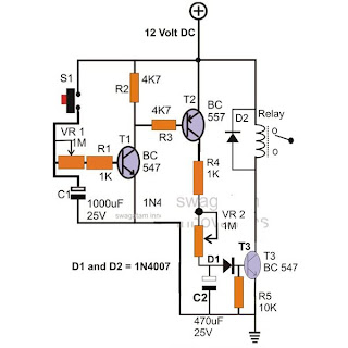

The circuit can be used for generating delays at a desired rate. The On time of the relay can be controlled by adjusting the Pot VR1 while the pot VR2 may be used to decide after how long the relay responds once theinput trigger is fed by the switch S1.

The parts list is enclosed inside the diagram.

Simple High and Low Mains Voltage Cut Off Circuit


Are you having problems with your input Mains supply? That’s common problem associated with our input mains AC line, where a high and a low voltage conditions are quite frequently encountered by us. The simple circuit shown here can be built and installed in you house electrical board for getting a 24/7 safety from the possible dangerous AC voltage conditions. The circuit keeps the relay and the wired appliances as long as the mains input stays within a safe tolerable level and switches the load OFF the moment a dangerous or unfavorable voltage condition is sensed by the circuit.

Parts List

R1, R2 = 1K,
P1, P2 = 10K Preset,
T1, T2 = BC547B,
C1 = 100uF/25V,
D1 = 1N4007
RL1 = 12V, SPDT,
TR1 = 0-12V, 500mA
0 – 40 V, 0 – 4 Amp Continuously Variable Power SupplyCircuit


This unique work bench circuit utilizes only a few inexpensive transistors and yet delivers some truly useful features. The feature includes continuously variable voltage from zero to the maximum transformer voltage and current variable from zero to the maximum applied input level. The output of this power supply is also over load protected. The pot P1 is used for setting the maximum current while the pot P2 is used for varying the output voltage level up to the desired levels.

Parts List
R1 = 1K2,
R2 = 100 Ohms,
R3 = 470 Ohms,
R4 = Evaluate using Ohms law.
R5 = 1K8,
R6 = 4k7,
R7 = 68 Ohms,
R8 = 1k8,
T1 = 2N3055,
T2, T3 = BC 547B,
D1 = 1N4007,
D2, D3, D4, D5 = 1N5408,
C1, C2 = 2200uF/50V,
Tr1 = 0 – 35 Volts, 3 Amp

Simple Crystal Tester Circuit

When it comes to frequency generating circuits or rather precise oscillator circuits, crystals become a crucial part, especially because they play an important role for generating and maintaining accurate frequency rates of the particular circuit. However these devices are prone to many defects and are normally difficult to check through conventional DMM units.

The shown circuit can be used for checking all types of crystals instantly. The circuit itself is a small transistor oscillator circuit which starts oscillating when a good crystal is introduced across the indicated points in the circuit. If the crystal is a good one, the bulb lights up showing the relevant results and if there’s any defect in the attached crystal, the bulb remains switched OFF.

Simple Current Limiter Circuit Using two transistors

In many critical applications, circuits are required to maintain a strict controlled magnitude of current through them of at their outputs. The proposed circuit is exactly meant for carrying out the discussed function. The lower transistor is the main output transistor which operates the output vulnerable load and by itself is unable to control the current through it. The introduction of the upper transistor makes it sure that the base of the lower transistor is allowed to conduct as long as the current output is within the specified limits. In case the current tends to cross the limits, the upper transistor conducts and switches OFF the lower transistor inhibiting any further passage of the exceeded current limit. The threshold current may be fixed by R which is calculated with the shown formula.